EasyManuals Logo

Piper Lance II User Manual

Piper Lance II
568 pages
To Next Page IconTo Next Page
To Previous Page IconTo Previous Page
Page #552 background imageLoading...
Page #552 background image
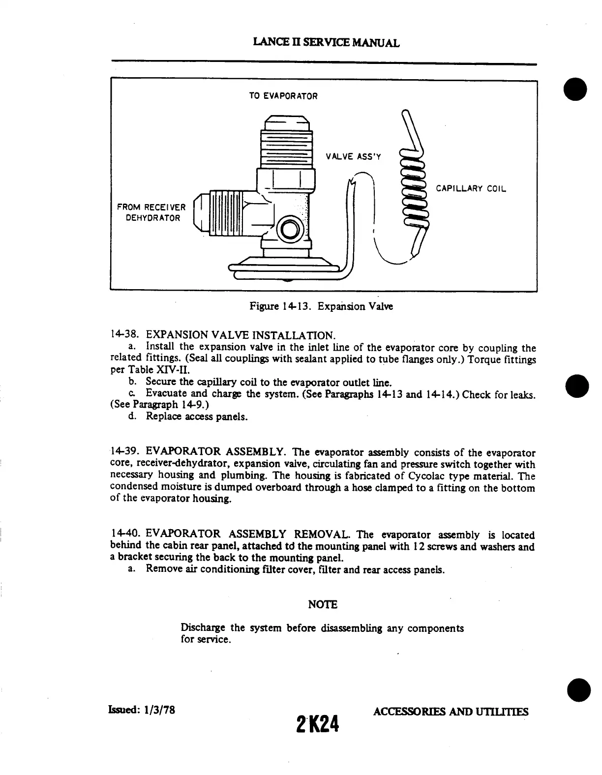
FROM
RECEIVER
DEHYDRATOR
LANCE
II
SERVICE
MANUAL
TO
EVAPORATOR
VALVE
ASS'Y
CAPILLARY
COIL
Figure
14-13.
Expansion
Valve
14-38.
EXPANSION
VALVE
INSTALLATION.
a.
Install
the
expansion
valve
in
the
inlet
line
of
the
evaporator
core
by
coupling
the
related
fittings.
(Seal
all
couplings
with
sealant
applied
to tube
flanges
only.)
Torque
fittings
per
Table
XIV-II.
b.
Secure
the
capillary
coil
to
the
evaporator
outlet
line.
c.
Evacuate
and
charge
the
system.
(See
Paragraphs
14-13
and
14-14.)
Check
for
leaks.
(See
Paragraph
14-9.)
d.
Replace
access
panels.
14-39.
EVAPORATOR
ASSEMBLY.
The
evaporator
assembly
consists
of
the
evaporator
core,
receiver-dehydrator,
expansion
valve,
circulating
fan
and
pressure
switch
together
with
necessary
housing
and
plumbing.
The
housing
is fabricated
of
Cycolac
type
material.
The
condensed
moisture
is
dumped
overboard
through
a hose
clamped
to a
fitting
on
the
bottom
of
the
evaporator
housing.
14-40.
EVAPORATOR
ASSEMBLY
REMOVAL.
The
evaporator
assembly
is located
behind
the
cabin
rear
panel,
attached
td the
mounting
panel
with
12
screws
and
washers
and
a bracket
securing
the
back
to
the
mounting
panel.
a.
Remove
air
conditioning
filter
cover,
filter
and
rear
access
panels.
NOTE
Discharge
the
system
before
disassembling
any
components
for
service.
Issued:
1/3/78
2K24
ACCESSORIES
AND
UTILITIES

Table of Contents

Questions and Answers:

Question and Answer IconNeed help?

Do you have a question about the Piper Lance II and is the answer not in the manual?

Piper Lance II Specifications

General IconGeneral
ManufacturerPiper Aircraft
Max Takeoff Weight3, 600 lb (1, 633 kg)
Crew1
Horsepower300 hp
Seats6
Length27 ft 7 in (8.41 m)
Capacity5 passengers

Related product manuals