ENGLISH
11
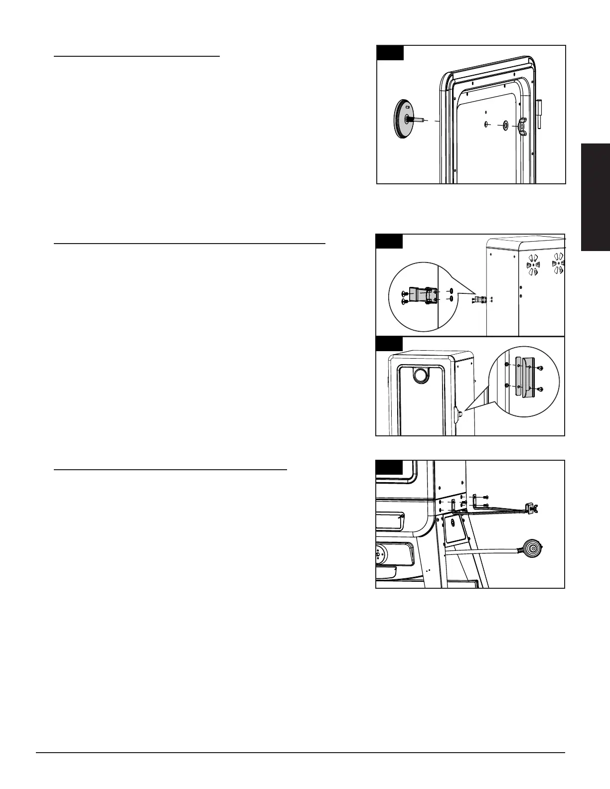
10.
Parts Required:
1 x Heat Indicator (#5)
1 x Cabinet Door (#9)
Installation:
• Remove the washer and wing nut from the packaged Heat Indicator.
• Insert the Heat Indicator into the mounting hole on the front of the
cabinet door, place the washer on the thread pole on the inside of the
door, and hand-tighten by hand to secure.
NOTE: The Heat Indicator is supplied with one washer and one wing
nut.
11. ,
Parts Required:
1 x Cabinet Door Handle Gasket (#6)
1 x Cabinet Door Handle (#7)
1 x Cabinet Door Latch (#8)
4 x Screw (#C)
Installation:
• First, re-mount the cabinet door to the main cabinet by aligning and
securing both hinges. Ensure the door is mounted correctly by testing
it opens freely.
• Mount the cabinet door handle onto the front side of the cabinet door
using two screws. Note correct direction in 11.
• Mount the cabinet door latch onto the exterior side of the main
cabinet using two screws. Note 11.
12.
Parts Required:
1 x Gas Cylinder Retainer Bracket (#18)
4 x Screw (#B)
Installation:
• Mount Gas Cylinder Retainer Bracket onto the Main Cabinet using four
screws as shown in illustration.
1
BRACKET INTO THE LOWER SMOKER
CABINET ASSEMBLY
Parts Required:
1 x Lower Smoker Cabinet Assembly (#14)
Installation:
(#17) to the Lower Smoker Cabinet
Fig.15
5.2 shown.
1
.
ASSEMBLY INTO THE LOWER
SMOKER CABINET ASSEMBLY
Parts Required:
1 x Wood Chip Box Lid (#11)
1 x Wood Chip Box Assembly (#12)
1 x Lower Smoker Cabinet Assembly (#14)
Installation:
•Put the Wood Chip Box Lid (#11) on
the Wood Chip Box Assembly (#12)
and slide Wood Chip Box onto the
Wood Chip Box support rails of Lower
Smoker Cabinet Assembly (#14) as
Fig.16 shown.
1
BRACKET INTO THE LOWER SMOKER
CABINET ASSEMBLY
Parts Required:
1 x Lower Smoker Cabinet Assembly (#14)
Installation:
(#17) to the Lower Smoker Cabinet
Fig.15
5.2 shown.
1
.
ASSEMBLY INTO THE LOWER
SMOKER CABINET ASSEMBLY
Parts Required:
1 x Wood Chip Box Lid (#11)
1 x Wood Chip Box Assembly (#12)
1 x Lower Smoker Cabinet Assembly (#14)
Installation:
•Put the Wood Chip Box Lid (#11) on
the Wood Chip Box Assembly (#12)
and slide Wood Chip Box onto the
Wood Chip Box support rails of Lower
Smoker Cabinet Assembly (#14) as
Fig.16 shown.
10
1
.
MOUNTING DOOR LATCH ASSEMBLY
TO THE UPPER SMOKER CABINET
ASSEMBLY
Parts Required:
2 x #10-24*1/2”(#C)
Installation:
(#2) using 2 x #10-24*1/2”(#C) as
Fig.1
shown.
12.
INSERTING HEAT INDICATOR INTO
THE DOOR ASSEMBLY
Parts Required:
1 x Door Assembly (#10)
1 X Heat
Installation:
•
the mounting hole in
by hand as Fig.12 shown.
1
.
MOUNTING DOOR HANDLE TO THE
DOOR ASSEMBLY
Parts Required:
1 x Door Handle (#7)
1 x Silicon Washer (#8)
1 X Door Assembly (#10)
2 x #10-24*1/2”(#C)
Installation:
• Attach the Door Handle (#7) with Silicon
Washer (#8) to the Door Assembly (#10)
using 2 x #10-24*1/2”(#C) as Fig.14
shown.
11
11
12
5
9
1
.
MOUNTING DOOR LATCH ASSEMBLY
TO THE UPPER SMOKER CABINET
ASSEMBLY
Parts Required:
2 x #10-24*1/2”(#C)
Installation:
(#2) using 2 x #10-24*1/2”(#C) as
Fig.1
shown.
12.
INSERTING HEAT INDICATOR INTO
THE DOOR ASSEMBLY
Parts Required:
1 x Door Assembly (#10)
1 X Heat
Installation:
•
the mounting hole in
by hand as Fig.12 shown.
1
.
MOUNTING DOOR HANDLE TO THE
DOOR ASSEMBLY
Parts Required:
1 x Door Handle (#7)
1 x Silicon Washer (#8)
1 X Door Assembly (#10)
2 x #10-24*1/2”(#C)
Installation:
• Attach the Door Handle (#7) with Silicon
Washer (#8) to the Door Assembly (#10)
using 2 x #10-24*1/2”(#C) as Fig.14
shown.
1
.
MOUNTING DOOR LATCH ASSEMBLY
TO THE UPPER SMOKER CABINET
ASSEMBLY
Parts Required:
2 x #10-24*1/2”(#C)
Installation:
(#2) using 2 x #10-24*1/2”(#C) as
Fig.1
shown.
12.
INSERTING HEAT INDICATOR INTO
THE DOOR ASSEMBLY
Parts Required:
1 x Door Assembly (#10)
1 X Heat
Installation:
•
the mounting hole in
by hand as Fig.12 shown.
1 .
MOUNTING DOOR HANDLE TO THE
DOOR ASSEMBLY
Parts Required:
1 x Door Handle (#7)
1 x Silicon Washer (#8)
1 X Door Assembly (#10)
2 x #10-24*1/2”(#C)
Installation:
• Attach the Door Handle (#7) with Silicon
Washer (#8) to the Door Assembly (#10)
using 2 x #10-24*1/2”(#C) as Fig.14
shown.
1
.
MOUNTING DOOR LATCH ASSEMBLY
TO THE UPPER SMOKER CABINET
ASSEMBLY
Parts Required:
2 x #10-24*1/2”(#C)
Installation:
(#2) using 2 x #10-24*1/2”(#C) as
Fig.1
shown.
12.
INSERTING HEAT INDICATOR INTO
THE DOOR ASSEMBLY
Parts Required:
1 x Door Assembly (#10)
1 X Heat
Installation:
•
the mounting hole in
by hand as Fig.12 shown.
1 .
MOUNTING DOOR HANDLE TO THE
DOOR ASSEMBLY
Parts Required:
1 x Door Handle (#7)
1 x Silicon Washer (#8)
1 X Door Assembly (#10)
2 x #10-24*1/2”(#C)
Installation:
• Attach the Door Handle (#7) with Silicon
Washer (#8) to the Door Assembly (#10)
using 2 x #10-24*1/2”(#C) as Fig.14
shown.
8
6
7
18




 To Next Page