ENGLISH
8
2.
Parts Required:
2 x Screw (#C)
Installation:
• Near the Control Panel, loosen the two screws connecting the front
panel to the main cabinet.
• Using another two screws, secure the front panel sides to the front-
facing support legs. Once these screws are tight, re-tighten the two
screws that were previously loosened.
3.
Parts Required:
1 x Support Bar (#15)
4 x Screw (#C)
Installation:
• Install the Support Bar to the rear of the unit between the two rear
Support Legs. Secure using two screws on each side. Ensure the Support
Bar is place on the underside of the main cabinet, facing inwards. Note
illustration for Support Bar arrangement.
NOTE: The Support Bar with two holes along the bottom should be
on the same side of the unit as the power cord exits the Control
Panel (left side). This is important for later steps.
4.
Parts Required:
2 x Support Panel (#20)
8 x Screw (#C)
Installation:
• Install one Support Panel to the side of the unit between a front and
back support legs. Secure using two screws on each side. Ensure the
flat side of the Support Panel is facing outwards. Repeat the same
installation to mount the other support panel. Note illustration for
Support Panel arrangement.
7
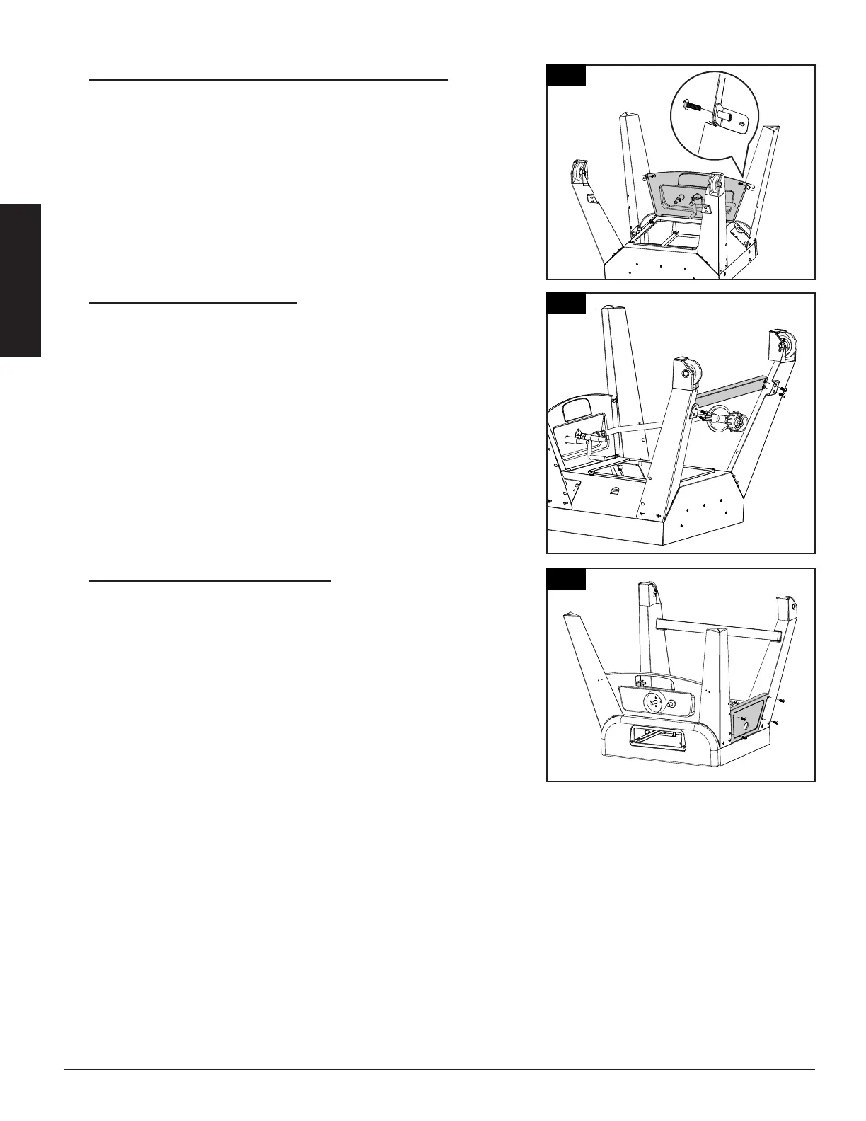
2.
MOUNTING BOTH FRONT LEGS TO
LOWER CABINET WITH CONTROL
PANEL ASSEMBLY
Parts Required:
1 x Lower Smoker Cabinet with
1 x Right Front Leg (#22)
1 x Left Front Leg (#21)
2 x #10-24*1/2”Screw (#C)
Installation:
rews which were
pre-assembled on the Control
to
Cabinet
mount Right Front Leg (#22)
Assembly (#14) using 2 x #10-24*1/2”Screws
(#C) and re-tighten 2 screws on the Control
Fig.2.1 shown.
3.
MOUNTING BACK SUPPORT TUBE TO
RIGHT REAR LEG WITH WHEEL
ASSEMBLY AND LEFT REAR LEG WITH
WHEEL ASSEMBLY
Parts Required:
1 x Back Support Tube (#23)
1 x Right Rear Leg with Wheel Assembly (#18)
1 x Left Rear Leg with Wheel Assembly (#20)
4 x #10-24*1/2”Screw (#C)
Installation:
• Mount Back Support Tube (#23) to the Right
Rear Leg with Wheel Assembly (#18) and Left
Rear Leg with Wheel Assembly (#20)using 4 x
#10-24*1/2”Screws (#C)as Fig.3 shown.
3
Installation:
Front Leg (#22)
#10-24*1/2”Screws (#C) as Fig.4 shown.
Leg (#21)
Assembly (#20) using 4 x
#10-24*1/2”Screws (#C) as Fig.4 shown.
5.
MOUNTING BURNER CHAMBER
ASSEMBLY TO THE BOTTOM AREA OF
LOWER SMOKER CABINET ASSEMBLY
Parts Required:
1 x Burner Chamber Assembly (#24)
1 x Lower Smoker Cabinet with Control
Panel Assembly (#14)
4 x #10-24*1/2”Screw (#C)
Installation:
• Attach ignition wire onto the pin end of
the Igniter on Control Panel.
Mount Burner Chamber Assembly (#24) to
the bottom area of Lower Smoker Cabinet
with Control Panel Assembly (#14) using 4
x #10-24*1/2”Screws (#C) as Fig.5.1 &
Fig.5.2 shown.
Note: MUST make sure
t
hat the tip of the valves
a
re completely INSIDE
t
he end opening of the
B
urner Tubes.
Note: Turn the Lower Smoker Cabinet with
Control Panel and Legs Assembly Right
Side Up as Fig.5.3 shown and tighten all
screws now.
4
15
20
20
7
2.
MOUNTING BOTH FRONT LEGS TO
LOWER CABINET WITH CONTROL
PANEL ASSEMBLY
Parts Required:
1 x Lower Smoker Cabinet with
1 x Right Front Leg (#22)
1 x Left Front Leg (#21)
2 x #10-24*1/2”Screw (#C)
Installation:
rews which were
pre-assembled on the Control
to
Cabinet
mount Right Front Leg (#22)
Assembly (#14) using 2 x #10-24*1/2”Screws
(#C) and re-tighten 2 screws on the Control
Fig.2.1 shown.
3.
MOUNTING BACK SUPPORT TUBE TO
RIGHT REAR LEG WITH WHEEL
ASSEMBLY AND LEFT REAR LEG WITH
WHEEL ASSEMBLY
Parts Required:
1 x Back Support Tube (#23)
1 x Right Rear Leg with Wheel Assembly (#18)
1 x Left Rear Leg with Wheel Assembly (#20)
4 x #10-24*1/2”Screw (#C)
Installation:
• Mount Back Support Tube (#23) to the Right
Rear Leg with Wheel Assembly (#18) and Left
Rear Leg with Wheel Assembly (#20)using 4 x
#10-24*1/2”Screws (#C)as Fig.3 shown.
2
7
2.
MOUNTING BOTH FRONT LEGS TO
LOWER CABINET WITH CONTROL
PANEL ASSEMBLY
Parts Required:
1 x Lower Smoker Cabinet with
1 x Right Front Leg (#22)
1 x Left Front Leg (#21)
2 x #10-24*1/2”Screw (#C)
Installation:
rews which were
pre-assembled on the Control
to
Cabinet
mount Right Front Leg (#22)
Assembly (#14) using 2 x #10-24*1/2”Screws
(#C) and re-tighten 2 screws on the Control
Fig.2.1 shown.
3.
MOUNTING BACK SUPPORT TUBE TO
RIGHT REAR LEG WITH WHEEL
ASSEMBLY AND LEFT REAR LEG WITH
WHEEL ASSEMBLY
Parts Required:
1 x Back Support Tube (#23)
1 x Right Rear Leg with Wheel Assembly (#18)
1 x Left Rear Leg with Wheel Assembly (#20)
4 x #10-24*1/2”Screw (#C)
Installation:
• Mount Back Support Tube (#23) to the Right
Rear Leg with Wheel Assembly (#18) and Left
Rear Leg with Wheel Assembly (#20)using 4 x
#10-24*1/2”Screws (#C)as Fig.3 shown.