ESPAÑOL
67
5.
Partes requeridas:
1 x Conjunto de la cámara inferior (#13)
4 x Tornillo (#C)
Instalación:
• Monte el conjunto de la cámara inferior en la parte inferior de la
base del armario con cuatro tornillos. Asegúrese de que los rieles de
la bandeja para la grasa estén orientados hacia la parte frontal de la
unidad. A continuación, conecte el cable de encendido en el extremo
del pasador del encendedor en el panel de control frontal de la unidad.
Observe la ilustración para un posicionamiento adecuado.
IMPORTANTE: La punta de las válvulas debe estar completamente
dentro de las aberturas de los tubos de los quemadores. Esto es
necesario para que el encendedor pueda encender el gas emitido por
los tubos del quemador en el conjunto de la cámara inferior.
• Proceda a apretar completamente todos los Tornillos en la base del
gabinete, luego gire con cuidado el carrito hacia arriba.
IMPORTANTE: Asegúrese de que todos los Tornillos en la base del
gabinete estén completamente apretados para evitar que los
Tornillos se caigan cuando se mueve la unidad.
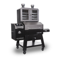
6.
Partes requeridas:
1 x Puerta del gabinete (#9)
1 x Gabinete principal (#10)
2 x Compuerta de ventilación (#3)
2 x Tornillo (#C)
2 x Tuerca de seguridad (#D)
2 x Arandelas de retención (#E)
Instalación:
• Primero, levante la puerta de la parrilla principal de las bisagras y
colóquela a un lado. Nota 6.
• Coloque un tornillo desde el exterior de la parrilla principal en el centro
de cada compuerta. Luego, inserte una compuerta dentro de la parrilla
principal con la pestaña levantada hacia la parte trasera , y asegure el
tornillo desde el exterior con una arandela de seguridad y una tuerca
de seguridad. Repita la misma instalación para la segunda compuerta,
como se muestra en la ilustración 6.
Installation:
Front Leg (#22)
#10-24*1/2”Screws (#C) as Fig.4 shown.
Leg (#21)
Assembly (#20) using 4 x
#10-24*1/2”Screws (#C) as Fig.4 shown.
5.
MOUNTING BURNER CHAMBER
ASSEMBLY TO THE BOTTOM AREA OF
LOWER SMOKER CABINET ASSEMBLY
Parts Required:
1 x Burner Chamber Assembly (#24)
1 x Lower Smoker Cabinet with Control
Panel Assembly (#14)
4 x #10-24*1/2”Screw (#C)
Installation:
• Attach ignition wire onto the pin end of
the Igniter on Control Panel.
Mount Burner Chamber Assembly (#24) to
the bottom area of Lower Smoker Cabinet
with Control Panel Assembly (#14) using 4
x #10-24*1/2”Screws (#C) as Fig.5.1 &
Fig.5.2 shown.
Note: MUST make sure
t
hat the tip of the valves
a
re completely INSIDE
t
he end opening of the
B
urner Tubes.
Note: Turn the Lower Smoker Cabinet with
Control Panel and Legs Assembly Right
Side Up as Fig.5.3 shown and tighten all
screws now.
5
13
Installation:
Front Leg (#22)
#10-24*1/2”Screws (#C) as Fig.4 shown.
Leg (#21)
Assembly (#20) using 4 x
#10-24*1/2”Screws (#C) as Fig.4 shown.
5.
MOUNTING BURNER CHAMBER
ASSEMBLY TO THE BOTTOM AREA OF
LOWER SMOKER CABINET ASSEMBLY
Parts Required:
1 x Burner Chamber Assembly (#24)
1 x Lower Smoker Cabinet with Control
Panel Assembly (#14)
4 x #10-24*1/2”Screw (#C)
Installation:
• Attach ignition wire onto the pin end of
the Igniter on Control Panel.
Mount Burner Chamber Assembly (#24) to
the bottom area of Lower Smoker Cabinet
with Control Panel Assembly (#14) using 4
x #10-24*1/2”Screws (#C) as Fig.5.1 &
Fig.5.2 shown.
N
ote
:
M
U
S
T
m
a
k
e
s
u
r
e
t
h
a
t th
e t
i
p
o
f
t
h
e v
a
l
ve
s
a
r
e c
o
mp
l
e
t
el
y
I
N
S
I
D
E
t
h
e
e
nd
o
p
e
n
i
n
g
o
f
t
h
e
B
u
r
n
e
r
T
u
b
e
s
.
Note: Turn the Lower Smoker Cabinet with
Control Panel and Legs Assembly Right
Side Up as Fig.5.3 shown and tighten all
screws now.
.
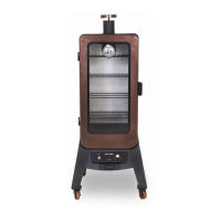
SMOKER CABINET ASSEMBLY
Parts Required:
1 x Upper Smoker Cabinet Assembly (#2)
2 x #10-24*1/2”Screw (#C)
Installation:
• the Assembly (#10) and set
aside. Mount
(#1) to the
Upper Smoker Cabinet Assembly (#2)
using 2 x #10-24*1/2”Screws (#C), 2 x
2 x #10-24
Lock Nut
.
UPPER SMOKER CABINET ASSEMBLY
Parts Required:
1 x Upper Smoker Cabinet Assembly (#2)
Installation:
• to the Upper
Smoker Cabinet Assembly (#2) using 4 x
. UPPER SMOKER
CABINET ASSEMBLY TO THE
LOWER SMOKER CABINET
ASSEMBLY
Parts Required:
1 x Upper Smoker Cabinet Assembly (#2)
1 x Lower Smoker Cabinet Assembly (#14)
6 x #10-24*1/2”(#C)
Installation:
• Mount Upper Smoker Cabinet Assembly
(#2)to the Lower Smoker Cabinet Assembly
(#14) using 6 x #10-24*1/2”(#C) as Fig.8.1 &
Fig.8.2 shown.
6
6
9
10
3
3