ENGLISH
9
5.
Parts Required:
1 x Bottom Chamber Assembly (#13)
4 x Screw (#C)
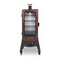
Installation:
• Mount the Bottom Chamber assembly to the bottom of the cabinet
base using four screws. Ensure the rails for the grease tray are facing
the front of the unit. Next, attach the ignition wire onto the pin end
of the igniter on the front control panel of the unit. Note illustration
for proper positioning.
IMPORTANT: The tip of the valves should be completely inside the
openings of the burner tubes. This is necessary so that the igniter
can light the gas emitted from the burner tubes in the Bottom
Chamber assembly.
• Proceed to fully-tighten all screws on the cabinet base, then carefully
turn the cart right side up.
IMPORTANT: Ensure that all screws on the cabinet base are fully-
tighten to avoid screws falling out when the unit is moved.
6.
Parts Required:
1 x Cabinet Door (#9)
1 x Main Cabinet (#10)
2 x Damper Vent (#3)
2 x Screw (#C)
2 x Lock Nut (#D)
2 x Locking Washer (#E)
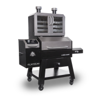
Installation:
• First, lift the main cabinet door off the hinges, and place aside. Note 6.
• Place one screw from the outside of the main cabinet into the center
of each damper. Next, insert a damper inside the main cabinet with
the raised tab facing the rear, and secure the screw from the exterior
using a locking washer and lock nut. Repeat same installation for
second damper, as shown in illustration 6.
7.
Parts Required:
1 x Back Handle (#4)
4 x Screw (#A)
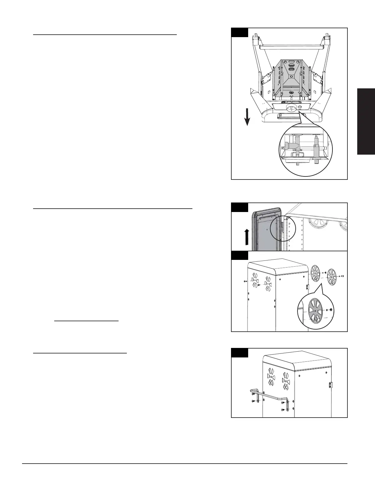
Installation:
• Mount the handle onto the back side of the main cabinet using four
screws. Note correct position as shown, with handle on top.
Installation:
Front Leg (#22)
#10-24*1/2”Screws (#C) as Fig.4 shown.
Leg (#21)
Assembly (#20) using 4 x
#10-24*1/2”Screws (#C) as Fig.4 shown.
5.
MOUNTING BURNER CHAMBER
ASSEMBLY TO THE BOTTOM AREA OF
LOWER SMOKER CABINET ASSEMBLY
Parts Required:
1 x Burner Chamber Assembly (#24)
1 x Lower Smoker Cabinet with Control
Panel Assembly (#14)
4 x #10-24*1/2”Screw (#C)
Installation:
• Attach ignition wire onto the pin end of
the Igniter on Control Panel.
Mount Burner Chamber Assembly (#24) to
the bottom area of Lower Smoker Cabinet
with Control Panel Assembly (#14) using 4
x #10-24*1/2”Screws (#C) as Fig.5.1 &
Fig.5.2 shown.
Note: MUST make sure
t
hat the tip of the valves
a
re completely INSIDE
t
he end opening of the
B
urner Tubes.
Note: Turn the Lower Smoker Cabinet with
Control Panel and Legs Assembly Right
Side Up as Fig.5.3 shown and tighten all
screws now.
5
13
Installation:
Front Leg (#22)
#10-24*1/2”Screws (#C) as Fig.4 shown.
Leg (#21)
Assembly (#20) using 4 x
#10-24*1/2”Screws (#C) as Fig.4 shown.
5.
MOUNTING BURNER CHAMBER
ASSEMBLY TO THE BOTTOM AREA OF
LOWER SMOKER CABINET ASSEMBLY
Parts Required:
1 x Burner Chamber Assembly (#24)
1 x Lower Smoker Cabinet with Control
Panel Assembly (#14)
4 x #10-24*1/2”Screw (#C)
Installation:
• Attach ignition wire onto the pin end of
the Igniter on Control Panel.
Mount Burner Chamber Assembly (#24) to
the bottom area of Lower Smoker Cabinet
with Control Panel Assembly (#14) using 4
x #10-24*1/2”Screws (#C) as Fig.5.1 &
Fig.5.2 shown.
N
ote
:
M
U
S
T
m
a
k
e
s
u
r
e
t
h
a
t th
e t
i
p
o
f
t
h
e v
a
l
ve
s
a
r
e c
o
mp
l
e
t
el
y
I
N
S
I
D
E
t
h
e
e
nd
o
p
e
n
i
n
g
o
f
t
h
e
B
u
r
n
e
r
T
u
b
e
s
.
Note: Turn the Lower Smoker Cabinet with
Control Panel and Legs Assembly Right
Side Up as Fig.5.3 shown and tighten all
screws now.
.
SMOKER CABINET ASSEMBLY
Parts Required:
1 x Upper Smoker Cabinet Assembly (#2)
2 x #10-24*1/2”Screw (#C)
Installation:
• the Assembly (#10) and set
aside. Mount
(#1) to the
Upper Smoker Cabinet Assembly (#2)
using 2 x #10-24*1/2”Screws (#C), 2 x
2 x #10-24
Lock Nut
.
UPPER SMOKER CABINET ASSEMBLY
Parts Required:
1 x Upper Smoker Cabinet Assembly (#2)
Installation:
• to the Upper
Smoker Cabinet Assembly (#2) using 4 x
. UPPER SMOKER
CABINET ASSEMBLY TO THE
LOWER SMOKER CABINET
ASSEMBLY
Parts Required:
1 x Upper Smoker Cabinet Assembly (#2)
1 x Lower Smoker Cabinet Assembly (#14)
6 x #10-24*1/2”(#C)
Installation:
• Mount Upper Smoker Cabinet Assembly
(#2)to the Lower Smoker Cabinet Assembly
(#14) using 6 x #10-24*1/2”(#C) as Fig.8.1 &
Fig.8.2 shown.
6
.
SMOKER CABINET ASSEMBLY
Parts Required:
1 x Upper Smoker Cabinet Assembly (#2)
2 x #10-24*1/2”Screw (#C)
Installation:
• the Assembly (#10) and set
aside. Mount
(#1) to the
Upper Smoker Cabinet Assembly (#2)
using 2 x #10-24*1/2”Screws (#C), 2 x
2 x #10-24
Lock Nut
.
UPPER SMOKER CABINET ASSEMBLY
Parts Required:
1 x Upper Smoker Cabinet Assembly (#2)
Installation:
• to the Upper
Smoker Cabinet Assembly (#2) using 4 x
. UPPER SMOKER
CABINET ASSEMBLY TO THE
LOWER SMOKER CABINET
ASSEMBLY
Parts Required:
1 x Upper Smoker Cabinet Assembly (#2)
1 x Lower Smoker Cabinet Assembly (#14)
6 x #10-24*1/2”(#C)
Installation:
• Mount Upper Smoker Cabinet Assembly
(#2)to the Lower Smoker Cabinet Assembly
(#14) using 6 x #10-24*1/2”(#C) as Fig.8.1 &
Fig.8.2 shown.
7
6
9
10
3
3
4