ESPAÑOL
66
2.
Partes requeridas:
2 x Tornillo (#C)
Instalación:
• Cerca del panel de control, afloje los dos tornillos ya ensamblados que
conectan el panel frontal al gabinete principal.
• Usando otros dos tornillos, asegure los lados del panel frontal a las
patas de soporte frontales. Una vez que los tornillos estén apretados,
vuelva a apretar los dos tornillos que se aflojaron previamente.
3.
Partes requeridas:
1 x Barra de suporte (#15)
4 x Tornillo (#C)
Instalación:
• Instale la barra de soporte en la parte posterior de la unidad, entre las
dos patas de soporte traseras. Asegure usando dos tornillos en cada
lado. Asegúrese de que la barra de soporte esté colocada en la parte
inferior del gabinete principal, volteada hacia adentro. Consulte la
ilustración para ver la disposición de la barra de soporte.
NOTA: La barra de soporte con dos orificios en la parte inferior debe
estar en el mismo lado de la unidad cuando el cable de alimentación
sale del panel de control (lado izquierdo). Esto es importante para los
pasos posteriores.
4.
Partes requeridas:
2 x Panel de suporte (#20)
8 x Tornillo (#C)
Instalación:
• Instale un panel de soporte en la parte lateral de la unidad, entre una
pata de soporte frontal y una trasera. Asegure usando dos tornillos en
cada lado. Asegúrese de que la superficie plana del panel de soporte
esté hacia afuera. Repita la misma instalación para montar el otro
panel de soporte. Consulte la ilustración para ver la disposición del
panel de soporte.
7
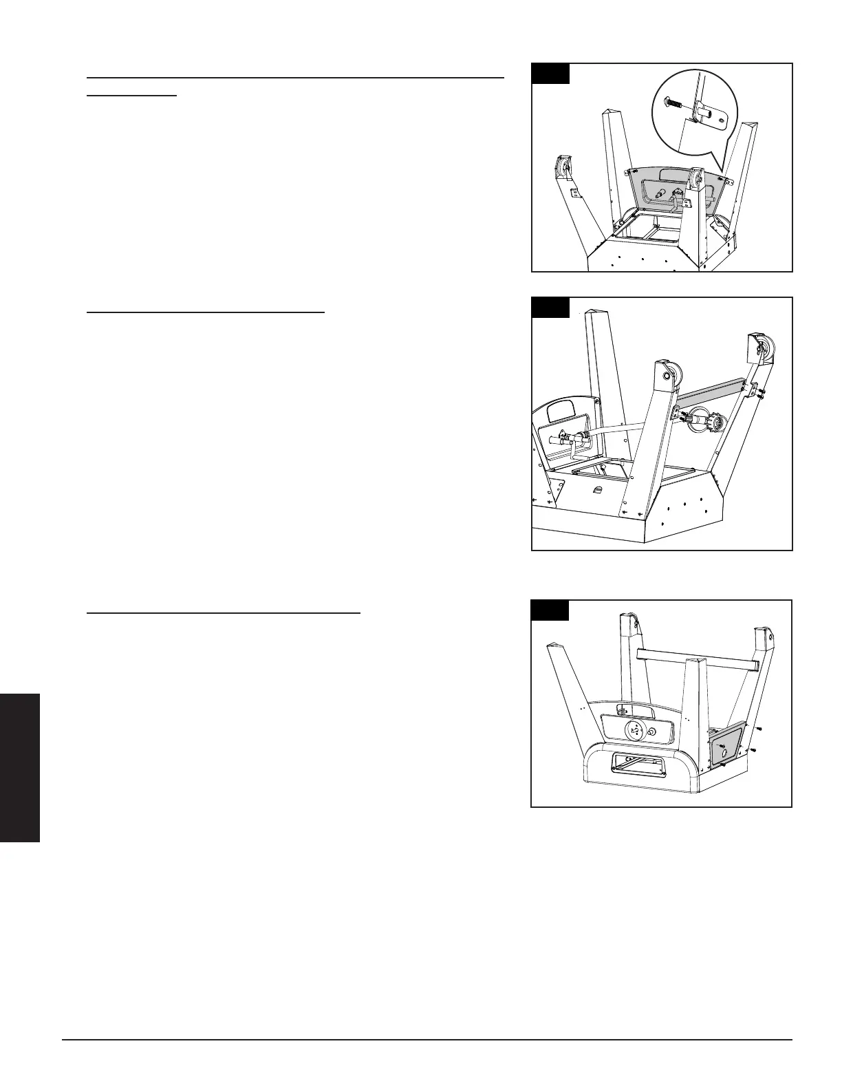
2.
MOUNTING BOTH FRONT LEGS TO
LOWER CABINET WITH CONTROL
PANEL ASSEMBLY
Parts Required:
1 x Lower Smoker Cabinet with
1 x Right Front Leg (#22)
1 x Left Front Leg (#21)
2 x #10-24*1/2”Screw (#C)
Installation:
rews which were
pre-assembled on the Control
to
Cabinet mount Right Front Leg (#22)
Assembly (#14) using 2 x #10-24*1/2”Screws
(#C) and re-tighten 2 screws on the Control
Fig.2.1 shown.
3.
MOUNTING BACK SUPPORT TUBE TO
RIGHT REAR LEG WITH WHEEL
ASSEMBLY AND LEFT REAR LEG WITH
WHEEL ASSEMBLY
Parts Required:
1 x Back Support Tube (#23)
1 x Right Rear Leg with Wheel Assembly (#18)
1 x Left Rear Leg with Wheel Assembly (#20)
4 x #10-24*1/2”Screw (#C)
Installation:
• Mount Back Support Tube (#23) to the Right
Rear Leg with Wheel Assembly (#18) and Left
Rear Leg with Wheel Assembly (#20)using 4 x
#10-24*1/2”Screws (#C)as Fig.3 shown.
3
Installation:
Front Leg (#22)
#10-24*1/2”Screws (#C) as Fig.4 shown.
Leg (#21)
Assembly (#20) using 4 x
#10-24*1/2”Screws (#C) as Fig.4 shown.
5.
MOUNTING BURNER CHAMBER
ASSEMBLY TO THE BOTTOM AREA OF
LOWER SMOKER CABINET ASSEMBLY
Parts Required:
1 x Burner Chamber Assembly (#24)
1 x Lower Smoker Cabinet with Control
Panel Assembly (#14)
4 x #10-24*1/2”Screw (#C)
Installation:
• Attach ignition wire onto the pin end of
the Igniter on Control Panel.
Mount Burner Chamber Assembly (#24) to
the bottom area of Lower Smoker Cabinet
with Control Panel Assembly (#14) using 4
x #10-24*1/2”Screws (#C) as Fig.5.1 &
Fig.5.2 shown.
Note: MUST make sure
t
hat the tip of the valves
a
re completely INSIDE
t
he end opening of the
B
urner Tubes.
Note: Turn the Lower Smoker Cabinet with
Control Panel and Legs Assembly Right
Side Up as Fig.5.3 shown and tighten all
screws now.
4
15
20
20
7
2.
MOUNTING BOTH FRONT LEGS TO
LOWER CABINET WITH CONTROL
PANEL ASSEMBLY
Parts Required:
1 x Lower Smoker Cabinet with
1 x Right Front Leg (#22)
1 x Left Front Leg (#21)
2 x #10-24*1/2”Screw (#C)
Installation:
rews which were
pre-assembled on the Control
to
Cabinet
mount Right Front Leg (#22)
Assembly (#14) using 2 x #10-24*1/2”Screws
(#C) and re-tighten 2 screws on the Control
Fig.2.1 shown.
3.
MOUNTING BACK SUPPORT TUBE TO
RIGHT REAR LEG WITH WHEEL
ASSEMBLY AND LEFT REAR LEG WITH
WHEEL ASSEMBLY
Parts Required:
1 x Back Support Tube (#23)
1 x Right Rear Leg with Wheel Assembly (#18)
1 x Left Rear Leg with Wheel Assembly (#20)
4 x #10-24*1/2”Screw (#C)
Installation:
• Mount Back Support Tube (#23) to the Right
Rear Leg with Wheel Assembly (#18) and Left
Rear Leg with Wheel Assembly (#20)using 4 x
#10-24*1/2”Screws (#C)as Fig.3 shown.
2
7
2.
MOUNTING BOTH FRONT LEGS TO
LOWER CABINET WITH CONTROL
PANEL ASSEMBLY
Parts Required:
1 x Lower Smoker Cabinet with
1 x Right Front Leg (#22)
1 x Left Front Leg (#21)
2 x #10-24*1/2”Screw (#C)
Installation:
rews which were
pre-assembled on the Control
to
Cabinet
mount Right Front Leg (#22)
Assembly (#14) using 2 x #10-24*1/2”Screws
(#C) and re-tighten 2 screws on the Control
Fig.2.1 shown.
3.
MOUNTING BACK SUPPORT TUBE TO
RIGHT REAR LEG WITH WHEEL
ASSEMBLY AND LEFT REAR LEG WITH
WHEEL ASSEMBLY
Parts Required:
1 x Back Support Tube (#23)
1 x Right Rear Leg with Wheel Assembly (#18)
1 x Left Rear Leg with Wheel Assembly (#20)
4 x #10-24*1/2”Screw (#C)
Installation:
• Mount Back Support Tube (#23) to the Right
Rear Leg with Wheel Assembly (#18) and Left
Rear Leg with Wheel Assembly (#20)using 4 x
#10-24*1/2”Screws (#C)as Fig.3 shown.