FRANÇAIS
37
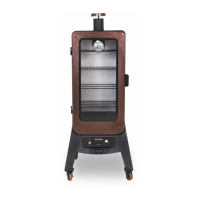
5.
Pièces nécessaires :
1 x Base de l'armoire (#13)
4 x Vis (#C)
Installation :
• Montez l'assemblage de la chambre inférieure au bas de la base de
l'armoire à l'aide de quatre vis. Assurez-vous que les rails du bac à
graisse font face à l'avant de l'unité. Ensuite, attachez le fil d'allumage
sur l'extrémité de la broche de l'allumeur sur le panneau de commande
avant de l'unité. Notez l'illustration pour un positionnement correct.
IMPORTANT : La pointe des vannes doit être complètement à
l'intérieur des ouvertures des tubes du brûleur. Ceci est nécessaire
pour que l'allumeur puisse allumer le gaz émis par les tubes du
brûleur dans l'assemblage de la chambre inférieure.
• Procédez au serrage complet de toutes les vis de la base de l'armoire,
puis tournez soigneusement le chariot côté droit vers le haut.
IMPORTANT: Assurez-vous que toutes les vis sur la base de l'armoire
sont bien serrées pour éviter que les vis ne tombent lorsque l'unité
est déplacée.
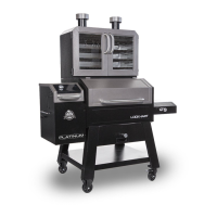
6. '
Pièces nécessaires :
1 x Porte d’armoire (#9)
1 x Armoire principale (#10)
2 x Registre de ventilation (#3)
2 x Vis (#C)
2 x Écrou (#D)
2 x Rondelle de blocage (#E)
Installation :
• D'abord, soulevez la porte de l'armoire principale hors des charnières et
mettez-la de côté. Illustration 6A.
• Placez une vis de l'extérieur de l'armoire principale dans le centre de
chaque registre. Ensuite, insérez un registre à l'intérieur de l'armoire
principale avec la languette surélevée vers l'arrière et fixez la vis de
l'extérieur à l'aide d'une rondelle-frein et d'un écrou de blocage. Répétez
le même processus pour le deuxième registre, comme indiqué sur
l'illustration 6B.
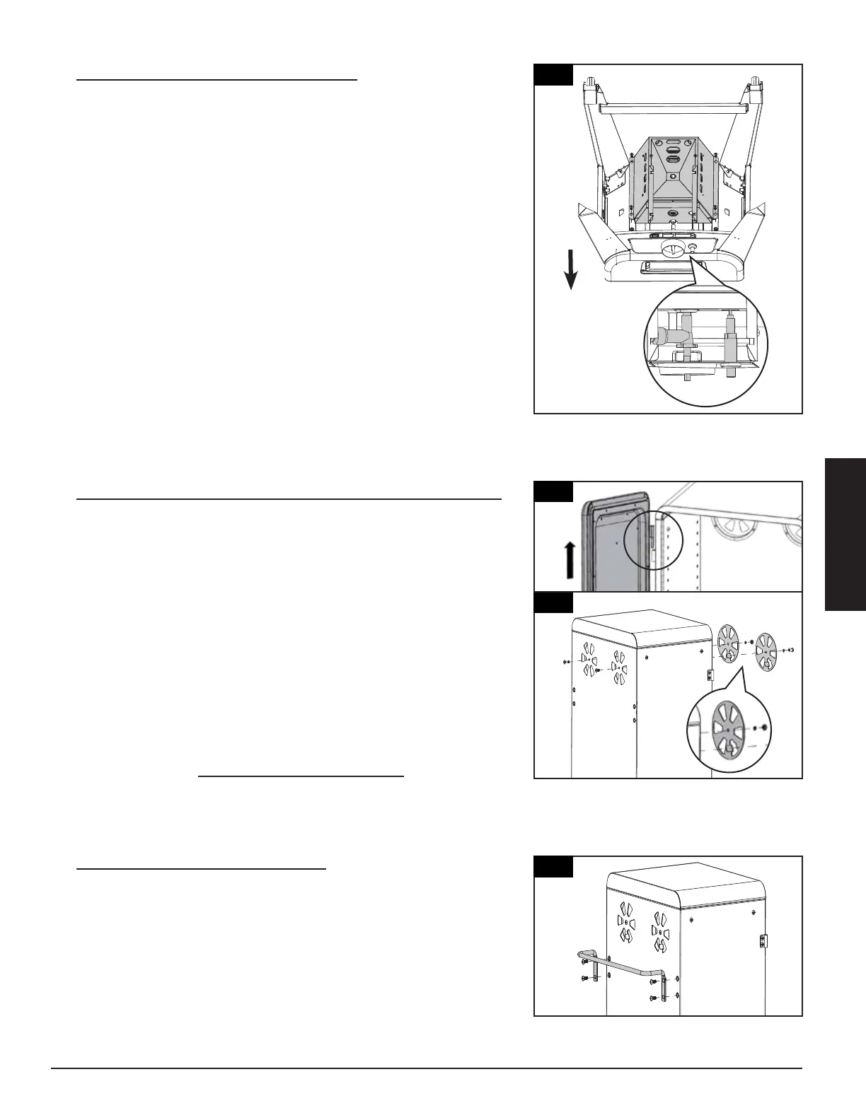
7.
Pièces nécessaires :
1 x Poignée arrière (#4)
4 x Vis (#A)
Installation :
• Montez la poignée au dos de l'armoire principale en utilisant quatre vis.
Regardez la position correcte indiquée, avec la poignée sur le dessus.
Installation:
Front Leg (#22)
#10-24*1/2”Screws (#C) as Fig.4 shown.
Leg (#21)
Assembly (#20) using 4 x
#10-24*1/2”Screws (#C) as Fig.4 shown.
5.
MOUNTING BURNER CHAMBER
ASSEMBLY TO THE BOTTOM AREA OF
LOWER SMOKER CABINET ASSEMBLY
Parts Required:
1 x Burner Chamber Assembly (#24)
1 x Lower Smoker Cabinet with Control
Panel Assembly (#14)
4 x #10-24*1/2”Screw (#C)
Installation:
• Attach ignition wire onto the pin end of
the Igniter on Control Panel.
Mount Burner Chamber Assembly (#24) to
the bottom area of Lower Smoker Cabinet
with Control Panel Assembly (#14) using 4
x #10-24*1/2”Screws (#C) as Fig.5.1 &
Fig.5.2 shown.
Note: MUST make sure
t
hat the tip of the valves
a
re completely INSIDE
t
he end opening of the
B
urner Tubes.
Note: Turn the Lower Smoker Cabinet with
Control Panel and Legs Assembly Right
Side Up as Fig.5.3 shown and tighten all
screws now.
5
13
Installation:
Front Leg (#22)
#10-24*1/2”Screws (#C) as Fig.4 shown.
Leg (#21)
Assembly (#20) using 4 x
#10-24*1/2”Screws (#C) as Fig.4 shown.
5.
MOUNTING BURNER CHAMBER
ASSEMBLY TO THE BOTTOM AREA OF
LOWER SMOKER CABINET ASSEMBLY
Parts Required:
1 x Burner Chamber Assembly (#24)
1 x Lower Smoker Cabinet with Control
Panel Assembly (#14)
4 x #10-24*1/2”Screw (#C)
Installation:
• Attach ignition wire onto the pin end of
the Igniter on Control Panel.
Mount Burner Chamber Assembly (#24) to
the bottom area of Lower Smoker Cabinet
with Control Panel Assembly (#14) using 4
x #10-24*1/2”Screws (#C) as Fig.5.1 &
Fig.5.2 shown.
N
ote
:
M
U
S
T
m
a
k
e
s
u
r
e
t
h
a
t th
e t
i
p
o
f
t
h
e v
a
l
ve
s
a
r
e c
o
mp
l
e
t
el
y
I
N
S
I
D
E
t
h
e
e
nd
o
p
e
n
i
n
g
o
f
t
h
e
B
u
r
n
e
r
T
u
b
e
s
.
Note: Turn the Lower Smoker Cabinet with
Control Panel and Legs Assembly Right
Side Up as Fig.5.3 shown and tighten all
screws now.
.
SMOKER CABINET ASSEMBLY
Parts Required:
1 x Upper Smoker Cabinet Assembly (#2)
2 x #10-24*1/2”Screw (#C)
Installation:
• the Assembly (#10) and set
aside. Mount
(#1) to the
Upper Smoker Cabinet Assembly (#2)
using 2 x #10-24*1/2”Screws (#C), 2 x
2 x #10-24
Lock Nut
.
UPPER SMOKER CABINET ASSEMBLY
Parts Required:
1 x Upper Smoker Cabinet Assembly (#2)
Installation:
• to the Upper
Smoker Cabinet Assembly (#2) using 4 x
. UPPER SMOKER
CABINET ASSEMBLY TO THE
LOWER SMOKER CABINET
ASSEMBLY
Parts Required:
1 x Upper Smoker Cabinet Assembly (#2)
1 x Lower Smoker Cabinet Assembly (#14)
6 x #10-24*1/2”(#C)
Installation:
• Mount Upper Smoker Cabinet Assembly
(#2)to the Lower Smoker Cabinet Assembly
(#14) using 6 x #10-24*1/2”(#C) as Fig.8.1 &
Fig.8.2 shown.
6
.
SMOKER CABINET ASSEMBLY
Parts Required:
1 x Upper Smoker Cabinet Assembly (#2)
2 x #10-24*1/2”Screw (#C)
Installation:
• the Assembly (#10) and set
aside. Mount
(#1) to the
Upper Smoker Cabinet Assembly (#2)
using 2 x #10-24*1/2”Screws (#C), 2 x
2 x #10-24
Lock Nut
.
UPPER SMOKER CABINET ASSEMBLY
Parts Required:
1 x Upper Smoker Cabinet Assembly (#2)
Installation:
• to the Upper
Smoker Cabinet Assembly (#2) using 4 x
. UPPER SMOKER
CABINET ASSEMBLY TO THE
LOWER SMOKER CABINET
ASSEMBLY
Parts Required:
1 x Upper Smoker Cabinet Assembly (#2)
1 x Lower Smoker Cabinet Assembly (#14)
6 x #10-24*1/2”(#C)
Installation:
• Mount Upper Smoker Cabinet Assembly
(#2)to the Lower Smoker Cabinet Assembly
(#14) using 6 x #10-24*1/2”(#C) as Fig.8.1 &
Fig.8.2 shown.
7
6
9
10
3
3
4