PN-0908073 Rev. 11 17-92
PS 164-2
THE ART OF WELDING
4. 2. Installation
4. 2. 1. Handling
The PS 164-2 comes with attached handles. Please
use these handles when moving the PS 164-2. Never
move it by pulling any cables or hoses.Movements
should be horizontal without sudden shocks or move-
ments. In case of using a truck, watch stability.
4. 2. 2. Installation
For safe work the PS 164-2 has to be placed horizon-
tally, on a fi rm surface. In this case a shaft system
ensures the stability of the machines.
If the equipment is used on a level which is not fl at,
be careful not to topple down the power source.
Openings are provided for ventilation of the power
source. To ensure effective cooling of the system, a
minimum distance of 30 cm (12") should be main-
tained between these openings and any surface.
4. 2. 3. Input power connection
All connections must be
made by a qualifi ed techni-
cian respecting the safety
rules given by law or
quoted in this manual.
General
The PS 164-2 is connected to the main power sup-
ply with a cable of 2 conductors + ground, which
comes with the machine. It is essential to connect
the ground cable correctly in order to ensure the
safety of the operators.
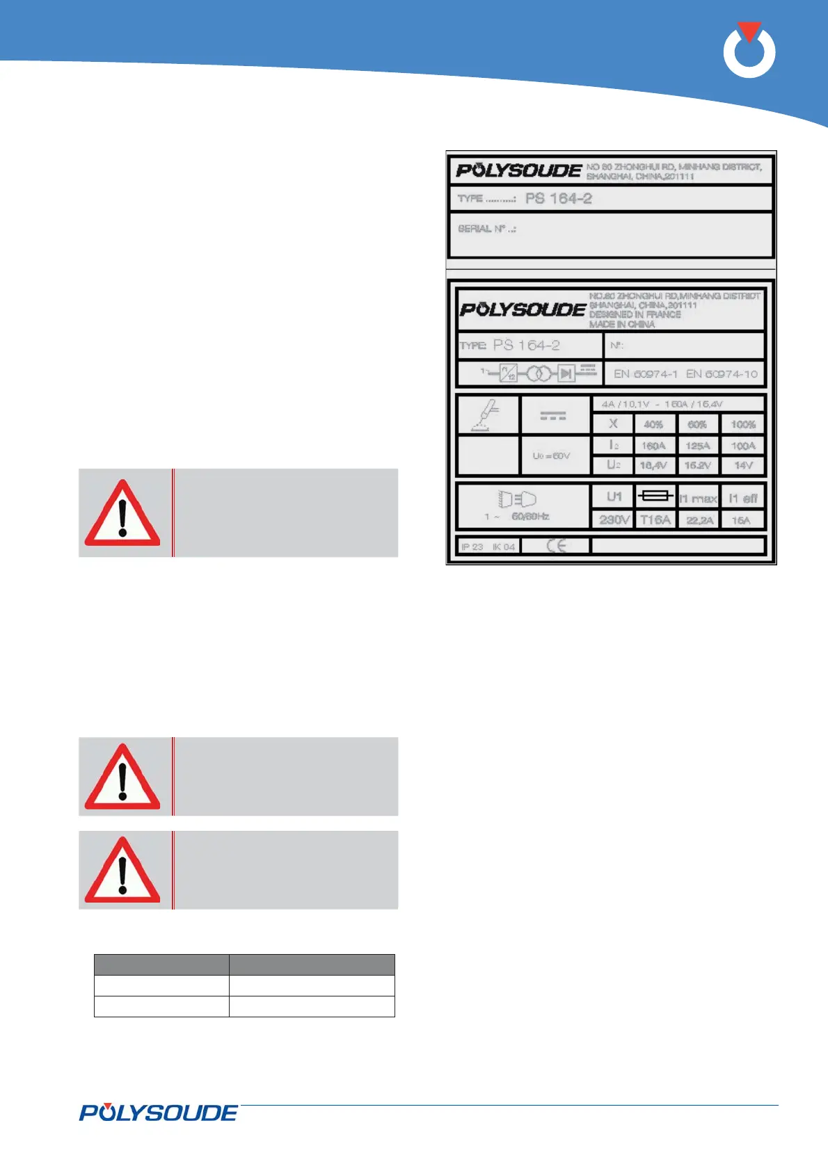
Refer to the name plate of your power source for in-
put power requirements. For example, to work with
an input Voltage of 230 V, a 16 A fuse is required.
It is essential to connect
the ground cable in order
to ensure the safety of the
operators.
If you use an extension
lead, please respect the
instructions below.
If you use an extension lead, the section of the lead
should be:
up to required section
20 m 3 x 2,5 mm²
50 m 3 x 4 mm².
Fig. 4.2 - Name plate of the PS 164-2 power source