PN-0908073 Rev. 11 51-92
PS 164-2
THE ART OF WELDING
5. 3. 9. 3. Deleting a program from the memo card
• Check that the key switch SY 26 is in the position
" Modifi cation authorised ".
• Choose any existing program in the source mem-
ory.
• Insert the memo card.
• Press the transfer button (symbol ).
• Press the button " trash " (symbol
), the name
of the fi rst program stored on the memo card is
shown on the display.
The keys SY 17 and SY 19 are used to scroll up and
down the program you wish to delete.
• Validate the transfer by pressing
. The corre-
sponding indicator will illuminate.
You can cancel the suppression of a programme by
pressing again the button " trash ".
5. 3. 10. Printing a program
To print a program from a memo card, the procedure
is as follows:
• With the switch BT 4 on the remote control
pendant, choose the number of the program to
print.
• Press the print button (symbol ).
• Validate. The printing indicator is illuminated.
• After the printing is fi nished, this indicator will ex-
tinguish.
5. 3. 11. Functioning modes
Modifi cations of the values of weld parameters can
be done in two different modes, one during devlop-
ment of a weld procedure and the second in produc-
tion.
◊ Modifying the parameters before starting a
program
To select this mode, turn the key operated switch
SY 26 to the "Modifi cation authorised" position (sym-
bol
). The key can be removed afterwards.
In this mode you can increase (+) or decrease (-)
during the weld cycle the values of the I22, V32 (for
no-pulsed speed rotation), V33 (for pulsed speed ro-
tation) or V42 parameters with the "Delta" buttons.
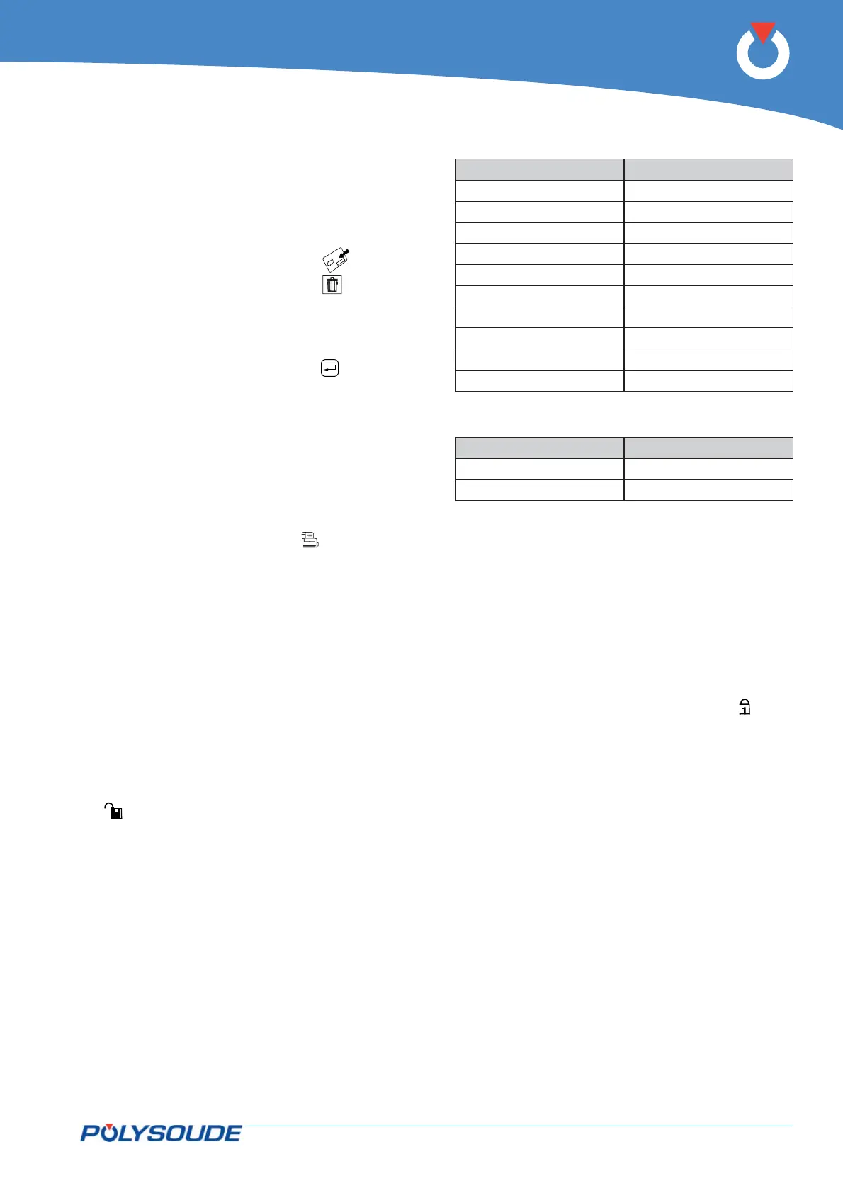
The modifi cation values of the delta buttons cannot
be changed by the user. It depends on the value of
the parameter which is being acted upon. The table
below gives the relationship between the parameter
value and the correction made by each press of the
delta button.
When a delta button is used, the value of the param-
eter concerned is displayed during 5 seconds on the
front face of the PS 164-2.
Wire feeder rotation speed :
Value of parameter Delta
≤ 99 1
100 - 199 2
200 – 299 3
300 – 399 4
400 – 499 5
500 – 599 6
600 – 699 7
700 – 799 8
800 – 899 9
900 – 999 10
Welding current :
Current range 160 A :
Value of I22 or I23 Position
≤99 1
100-160 2
Current range 50 A : Deltas I = 0,1 A
All actions on the delta buttons are taken into ac-
count (within the parameter limits) and stored in the
memory of the relevant sector. After moving from
one sector to another, the corrections made in the
preceding one are carried through to the next. The
modifi cations are not forgotten or lost. The number
of deltas in this mode is not limited.
Modifi cations made during the weld cycle.
To access the production mode, the key operated
switch SY 26 has to be turned to the "Program mod-
ifi cation not authorised" position (symbol
). The
key can be removed afterwards to avoid unauthor-
ised modifi cations being made to the programs.
This mode includes two differences:
• The number of deltas per parameter is limited to
10 (10 increments or 10 decrements)
• The modifi cations are not stored in the memory.
◊ Fault detecting during cycle
During every welding cycle, important parameter
values are monitored periodically at different deli-
cate points. When a fault is detected, an immediate
stop or a stop with downslope is initiated depending
on the seriousness of the fault. The fault is indicated
by a fl ashing light on the remote control pendant.
An error code will also appear on the display of the
PS 164-2. Appendix 7.2 gives the error codes, their
meaning and their consequences. We advise you to
take careful notice as to which error code is shown.
This can make maintenance or repair work easier
and highly effi cient.