74-92 PN-0908073 Rev. 11
PS 164-2
THE ART OF WELDING
1248
◊ The source
The power command, generated by the sequencer
card, is an analogical signal 0 to 10 V. At 10 V, it cor-
responds to 160 A, and at 0 V it corresponds to the
minimum current of the source, 4 A, for the 160 A
range; at 10 V it corresponds 50 A, and at 0 V it cor-
responds 4 A, for the 50 A range.
A logic order active at high level (15 V) controls the
running of the source.
The source sends a signal indicating that it is over-
heated. The signal is released by the sequencer card
to stop the weld cycle and display the code of the
detected fault (27).
The high frequency power source is controlled by a
signal emitted from the sequencer card. A relay con-
tact ensures that this action occurs. The other pole of
contact is linked to an alternative voltage of 42 V.
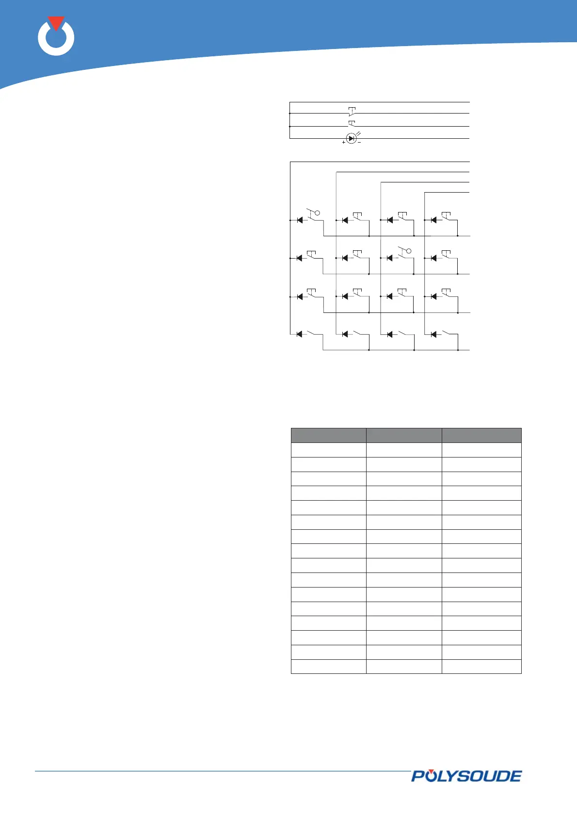
◊ The remote control pendant
The buttons on the control pendant are controlled
by the synoptic card (21700634). Most of the but-
tons are tested by the line and column method: A
high level signal is placed on a line and the columns
are tested. If a column is at a high level, this shows
that the button associated with this line and column
has been pressed. The next line is tested afterwards,
and so on. Only the two safety buttons are directly
linked.
The In cycle indicator is a light emitting diode LED.
Fig. 6.22 - Remote control pendant logic
LINE COLUMN BUTTON
11BT 1
1 2 BT 16
1 3 BT 11
1 4 BT 14
21BT 5
2 2 BT 15
2 3 BT 12
24BT 9
31BT 6
3 2 BT 10
3 3 BT 13
34BT 8
4 1 BT 4 (1)
4 2 BT 4 (2)
4 3 BT 4 (4)
4 4 BT 4 (8)
Emergency stop
Stop
In cycle
Column 1
Column 2
Column 3
Column 4
Line 1
Line 2
Line 3
Line 4