PN-0908073 Rev. 11 55-92
PS 164-2
THE ART OF WELDING
5. 4. 5. End of welding cycle
5. 4. 5. 1. Normal end of welding cycle
In the case of a normal end of the welding cycle,
the indicator on the remote control pendant extin-
guishes. The power source is now ready to start a
new cycle.
N.B.: welding head that is fi tted out with an
"open head" position sensor will be automati-
cally positioned in this way at the regular end
of a cycle.
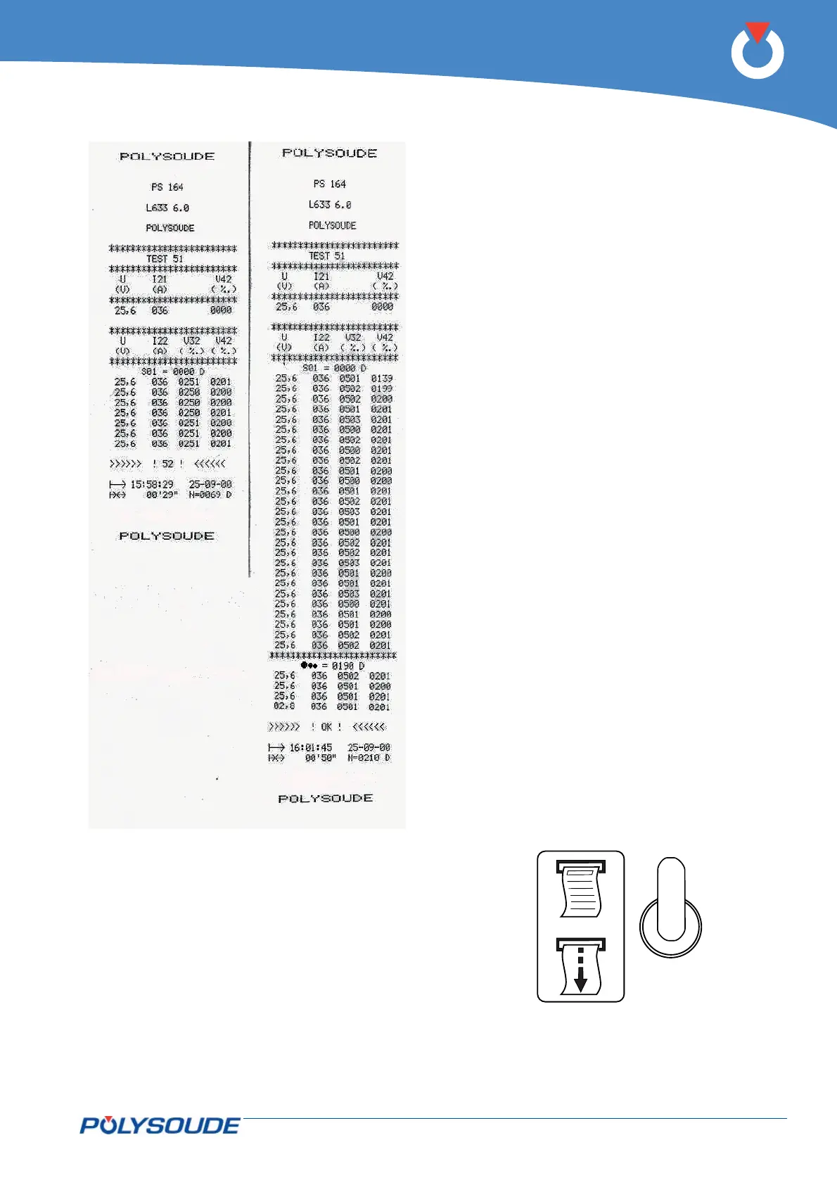
5. 4. 5. 2. Weld cycle report
At the end of every weld, you can print a weld cycle
report indicating periodically the real values of the
main weld parameters. This listing is provided au-
tomatically if preprogrammed. After a weld cycle in
simulation mode, no weld report can be given.
The weld cycle report consists of:
• The name of your company.
• The program name.
• Values of periodically taken measurements of the
voltage, amperage, rotation speed and wire speed
during the cycle.
• Reason for stop ("OK" for a normal cycle end, if
not, error code).
• Time of cycle start.
• Date of weld.
• Length of cycle.
• Tungsten location.
5. 4. 5. 3. Reprint of a weld cycle report
If the printout of a weld cycle report fails, for exam-
ple because of a lack of paper, it is possible to restart
it by pushing the switch SY 29 situated at the right
of the printer upwards.
Fig. 5.9 - Example of a
weld cycle report with
manual downslope,
denoted by error code
>>>> ! 52 ! <<<
Fig. 5.11 - Printer switch
Fig. 5.10 - Example
of a weld cycle report
with a normal cycle
end, denoted by
>>>> ! OK ! <<<<