SDI drives must be wired toward the control unit's SDI connector in
a daisy chain setup.
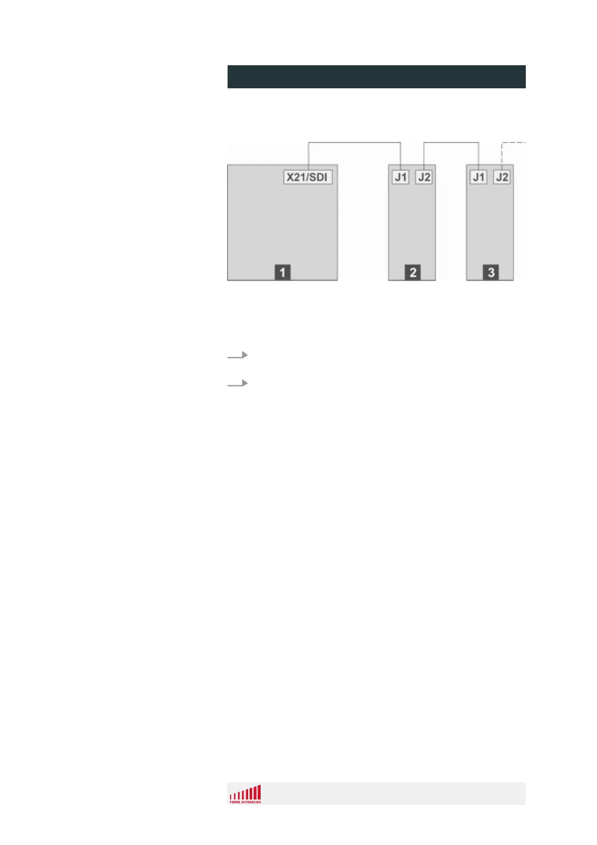
Fig. 23: Daisy chain setup
1 PA 8000 EL (control unit)
2
PA SDI Drive Midi
TM
or Maxi
TM
3
PA SDI Drive Midi
TM
or Maxi
TM
1. Connect the X21 connector of the control unit with the J1
connector of the first SDI drive.
2. Connect additional SDI drives via the J1 and J2 connectors
to each other and to the J2 connector of the first SDI drive as
shown in the schematic.
Further drives have to be connected via connector 'J2' of the pre-
vious drive to the connector 'J1' of the next drive.
Connection Requirements
PA 8000 EL CNC control unit
Design and function
24.09.2015 | 48
 Loading...