3.5 PC connectors
The control unit provides a number of standard PC interface con-
nectors for various input and output applications.
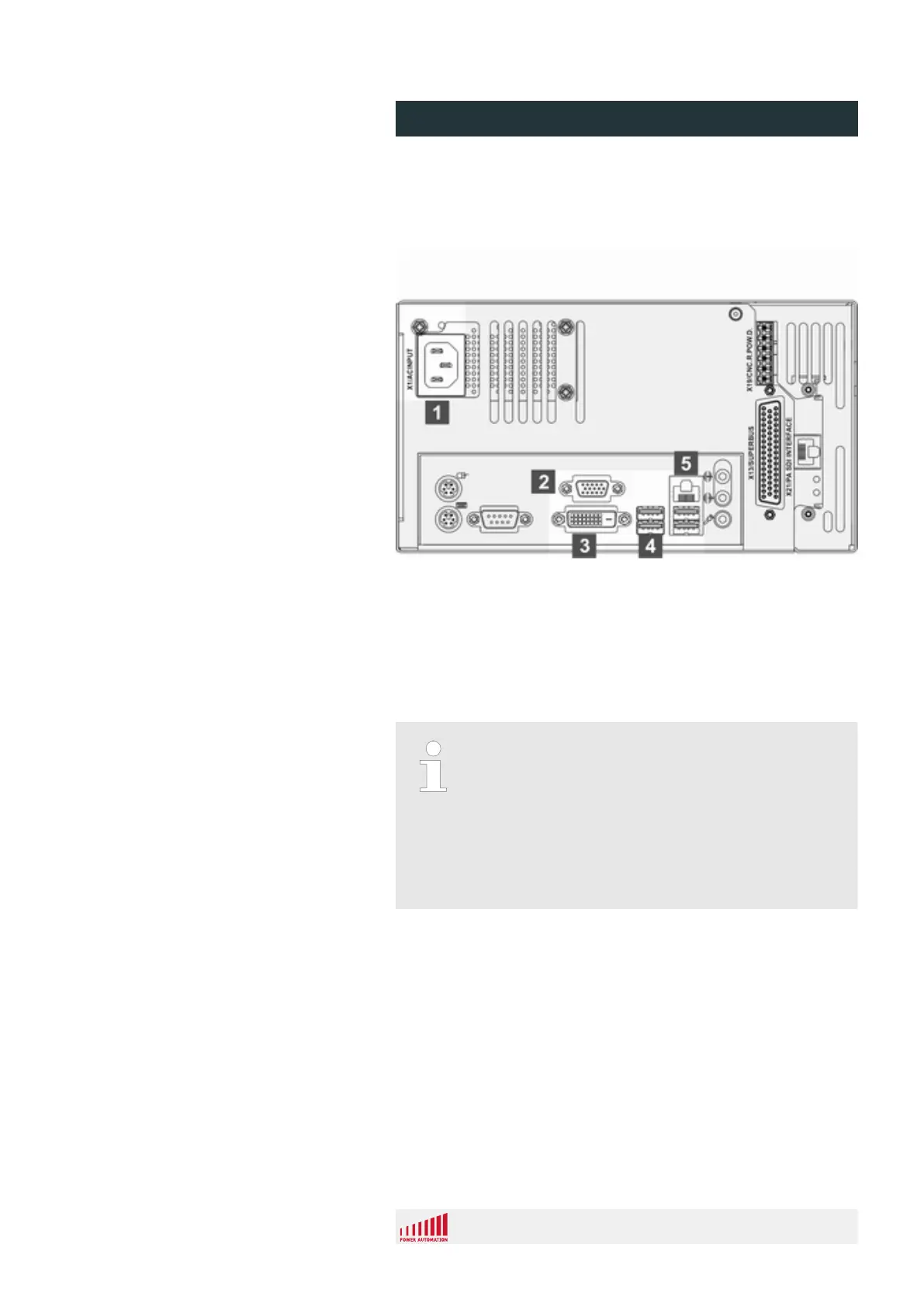
Fig. 24: Overviews PC connectors
1 Main power supply (X1)
2 VGA connector, Sub-D, 15 pin, male (X4)
3 DVI Connector (X4)
4 4 USB 2.0 connectors
5 Ethernet connector, RJ45
Hardware configuration subject to change
Due to varying configurations of the mainboards pro-
duced by the suppliers, the number and positions of
USB, serial and parallel ports may differ from the
example provided in this installation manual.
– For information on the applicable number of
interfaces see the specification provided in the
sales records.
Overview
PA 8000 EL CNC control unit
Design and function
24.09.2015 | 49
 Loading...