3.4 SDI interface
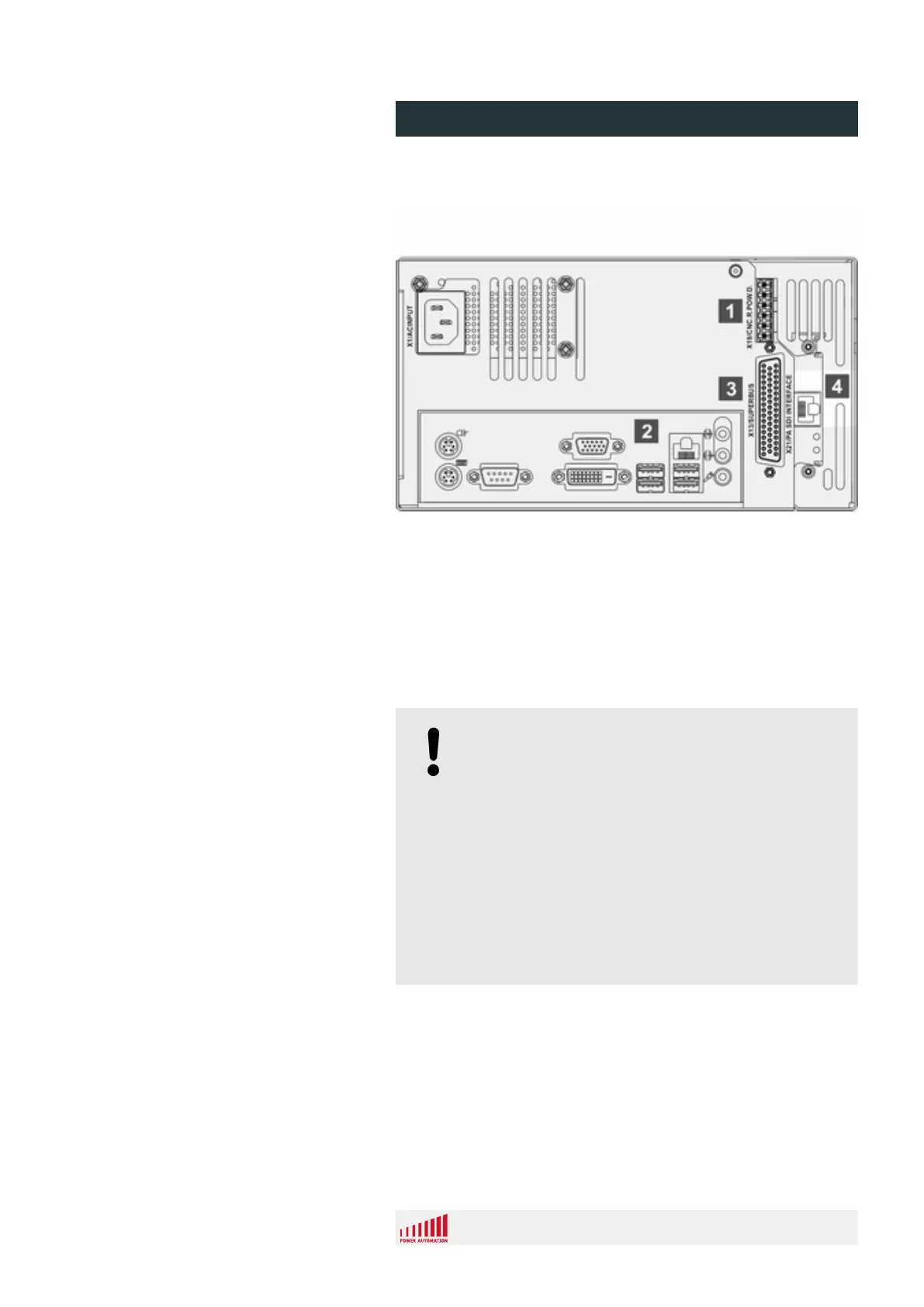
Fig. 22: SDI connector positions
1 Safety connector (X19)
2 PC connectors
3 Superbus connector (X13)
4 SDI connector (X21)
The hardware provides a single RJ 45 connector which is deter-
mined at connector X21 (Fig. 22/4, X21). This connector communi-
cates with the SDI-drives. The SDI bus is a serial bus for full cap-
turing of the axes position inputs and velocity command outputs.
NOTICE!
Malfunctions and damage to the control unit!
The control unit provides several RJ 45 connectors.
One or two are located on the PC interface panel
(Fig. 22/1) and only intended for Ethernet connections.
The other RJ 45 connector (Fig. 22/4) is located next
to the PAMIO superbus connector. Inadvertent inter-
changing of the two connectors can cause control unit
malfunctions and damages to the control unit and the
attached drives.
– When setting up the wiring, carefully observe the
connectors' positions given in this installation
manual as well as the labels on the control unit.
Overview
PA 8000 EL CNC control unit
Design and function
24.09.2015 | 47
 Loading...