n Install noise suppression components for all coils, relays,
valves, switching units, motor windings, other operator display
panels and other RF noise producing devices.
n Connect noise suppression components directly at the noise
source.
If the distance to noise suppression components is several
centimeters, use twisted pair cables to connect.
n Make sure, that noise suppressing capacitors have a low
inductance and a good high frequency conductance.
n Conduct power and signal lines separately in a distance of at
least 10 cm.
n When using mechanical cable guides, install additional metal
shields.
n For all electrical installations, follow the rules of VDE 0113.
5.3 Installing digital I/O
The following chapters provide instructions and examples for
installation of digital inputs and outputs. Due to the versatility of the
control unit not all possible configuration options can be covered in
detail.
n If in doubt, contact the Power Automation's customer support.
For contact information see
Ä
Chapter 9 “Service and return
process” on page 95.
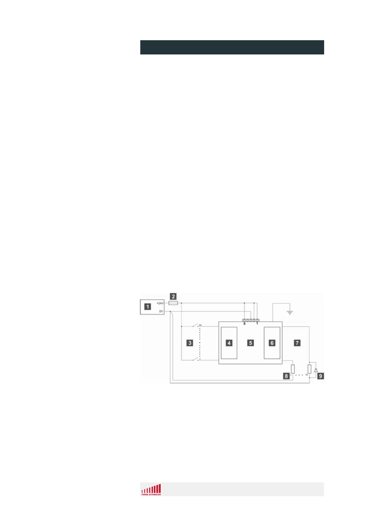
5.3.1 Wiring example for 2416EL modules
Fig. 44: Cabling example for 2416EL modules
1 Power supply
2 Fuse (slow)
3 Input signals
4 Inputs
5 Module 2416EL
6 Outputs
7 Output signals
8 Resistive load
9 Inductive load
RF Noise Suppression
General
Schematic
PA 8000 EL CNC control unit
Installation
24.09.2015 | 80
 Loading...