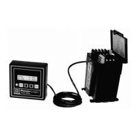
Power Meter Bulletin No. 3020IM9503R6/98
Chapter 1—Introduction December 1998
2 1998 Square D All Rights Reserved
Real-Time Readings
• Current (per phase)
• Voltage (L-L, L-N)
• Real Power (per phase and 3Ø total)
• Reactive Power (per phase and 3Ø total)
• Apparent Power (per phase and 3Ø total)
• Power Factor, true (per phase, 3Ø)
• Frequency
Energy Readings
• Accumulated Energy, real 3Ø total
• Accumulated Energy, reactive 3Ø total
• Accumulated Energy, apparent 3Ø total
Description Mfr./Part Number Quantity
RJ-11, 6-position, 4-conductor ➀
Mouser 154-UL6234
Round Cable Modular Plug
or 2 plugs
AMP 5-569031-3
Olflex 602604
Signal and Control Cable
or 50-ft. (15.2 m)
Unitronic 190 Maximum Length
(4-wire/26 AWG)
Type Description
PM-600 Instrumentation, 0.3% accuracy
PM-620 PM-600 features, plus date/time stamp, THD/thd,
neutral current, demand values
PM-650 PM-620 features, plus alarms, min/max values,
data and event logs
PMD-32 Power Meter Display (optional) with 1-ft. (0.3 m) cable
SC-104 4-ft (1.2 m) cable (optional)
SC-112 12-ft. (3.7 m) cable (optional)
SC-130 30-ft. (9.1 m) cable (optional)
Table 1-2
Class 3020 Power Meters and Accessories
Table 1-1
Summary of Power Meter Instrumentation
Table 1-3
Components for Assembling Custom Length Cables
Table 1-1 below summarizes the power meter instrumentation common to all
three models. Table 1-2 describes the three power meter models and accesso-
ries. You can assemble custom length cables using the components specified
in Table 1-3. Table 1-4 compares features of those models.
➀ Assemble with manufacturer’s recommended crimping tool.

 Loading...