Bulletin No. 3020IM9503R6/98 Power Meter
December 1998 Chapter 4—Installation
1998 Square D All Rights Reserved 15
!
CAUTION
HAZARD OF EQUIPMENT DAMAGE.
Use only the power meter display mounting screws included in the mount-
ing hardware kit. Use of any other screws for display mounting voids the
warranty and may damage the display.
Failure to observe this precaution can result in equipment damage.
5. Using the screws in the display hardware kit, secure the power meter to
the display through the bottom two mounting feet holes. Tighten all
screws to 6–9 lb-in (0.7–1.0 N•m).
6. Plug the other end of the communications cable into the display
communications port (terminal 22, figure 4-1) on the power meter.
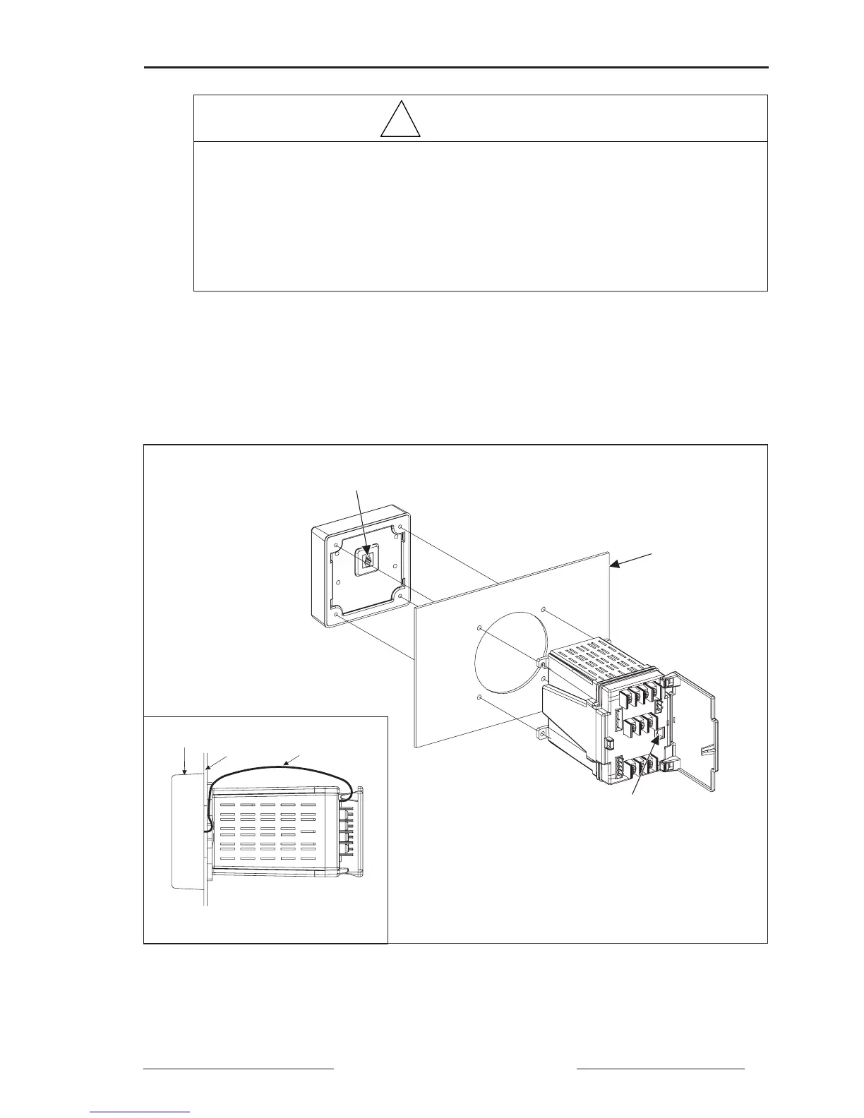
Figure 4-1: Mounting power meter and display on panel with existing ammeter/voltmeter cutout
Display Communications
Port (Terminal 23)
Panel with
Existing Cutout
Display
Panel
Display Cable
SC-101
Top View
After Mounting
Display Communications
Port (Terminal 22)