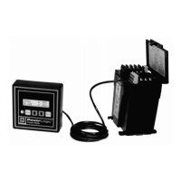
Power Meter Bulletin No. 3020IM9503R6/98
Chapter 5—Wiring December 1998
22 1998 Square D All Rights Reserved
Control Power Transformer (CPT) Sizing
If you are using control power transformers (CPTs), refer to table 5-2 below. It
shows CPT sizing for various quantities of power meter modules.
Control Power Fuses
The control power input(s) of each power meter module must be individually
fused under all circumstances. When using a control power transformer
where the secondary is 120 Vac, or when deriving control power from
metering potential transformers, use a standard 250 V, 100 mA, fast-acting
fuse. If control power is derived directly from the line voltage (600 V or less),
each power meter module control input must be fused using a 1/2 amp
Bussman FNQ-R fuse (or equivalent).
Metering Potential Transformers (PTs)
No potential transformers are required on the voltage metering inputs for
wye-connected and ungrounded delta circuits with line-to-line voltages of 600
V or less; connect the voltage metering inputs directly to the line voltages.
However, for power systems with voltages higher than 600 V line-to-line, or
corner-grounded delta circuits, potential transformers must be used. To set up
the appropriate voltage range, see page 50.
CE Compliance
To comply with CE Electromagnetic Compatibility Requirements, the power
meter must be installed in a metallic enclosure, i.e., switchgear. Install the
clamp-on ferrite provided in the hardware kit around all three control power
input leads close to the power meter (figure 5-1). To open the clamp-on ferrite
prior to installation, follow the instructions in figure 5-2.
For CE compliance, a Merlin Gerin Disconnect Breaker Type P25M #21104 or
IEC 947 equivalent must be connected directly to the metering voltage and
control power inputs (figure 5-1). Note: The disconnect switch must be placed
within reach of the power meter and labeled “Disconnect Switch for Power Meter.”
Number of Size of
Power Meter Modules CPT
1–10 100 VA
11–20 150 VA
21–30 200 VA
31–40 250 VA
Table 5-2
Control Power Transformer Sizing

 Loading...