Bulletin No. 3020IM9503R6/98 Power Meter
December 1998 Chapter 5—Wiring
1998 Square D All Rights Reserved 23
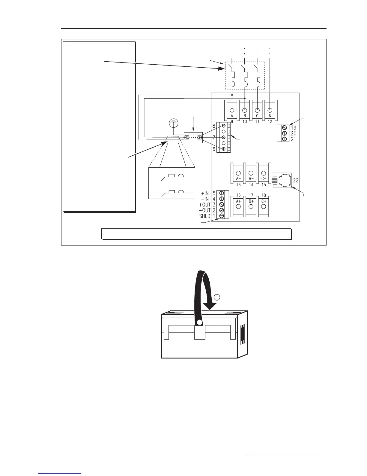
Figure 5-1: Clamp-on ferrite and disconnect breaker for CE compliance (4-wire system shown)
To open the clamp-on ferrite prior to installation, follow these steps:
1. Using a small screwdriver or similar device, gently pry open the ferrite case at
location ➀ above.
2. Flip open the top of the ferrite case in the direction shown (➁).
3. After routing control leads through the middle of the ferrite, snap the ferrite
case closed; make sure you do not crimp the control wires when closing
the ferrite case.
Figure 5-2: Opening the clamp-on ferrite
1
2
Display
Comms
Port
Voltage
Control
Power
Comms
Current
KYZ
Clamp-On
Ferrite
Metering Voltage Source
Note: See figures 5-3 through 5-8 for possible system connections.
Disconnect
Breaker
Note: The disconnect
breaker
must
be
installed here
If control power is derived
from the metering voltage
source, no additional
disconnect device is
necessary.
However, if control
power is derived from
a separate source (
not
jumpered from
metering voltage as
shown), an
additional
disconnect breaker
must
be installed here
between the control
power terminals and the
control power source
(See inset box at right
for detail of additional
disconnect breaker.)
L
1
L
2