Power Meter Bulletin No. 3020IM9503R6/98
Chapter 3—Hardware Description December 1998
8 1998 Square D All Rights Reserved
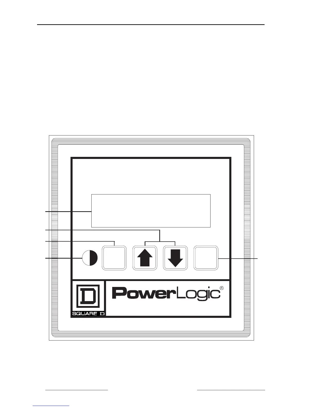
Figure 3-1: Power meter display components
Figure 3-1 shows the power meter display. Display components are listed
below:
➀ 2-Line Liquid Crystal Display. For local display of metered values.
➁ Arrow Buttons. Press to move through meter display screens. In Setup,
Resets, and Diagnostic modes, press to change values and, on the PM-650
only, Alarm Setup and Alarm Log.
➂ Mode Button. Press to scroll through the available modes.
➃ Contrast Button. Press to change the contrast of the display.
➄ Select Button. Press to select modes and Setup, Resets, and Diagnostic
values. On the PM-650 only, use this button to select Alarm values.
Power Meter
Mode
Select
➀
➂
➃
➁
➄