Bulletin No. 3020IM9503R6/98 Power Meter
December 1998 Chapter 9—Onboard Alarming
1998 Square D All Rights Reserved 67
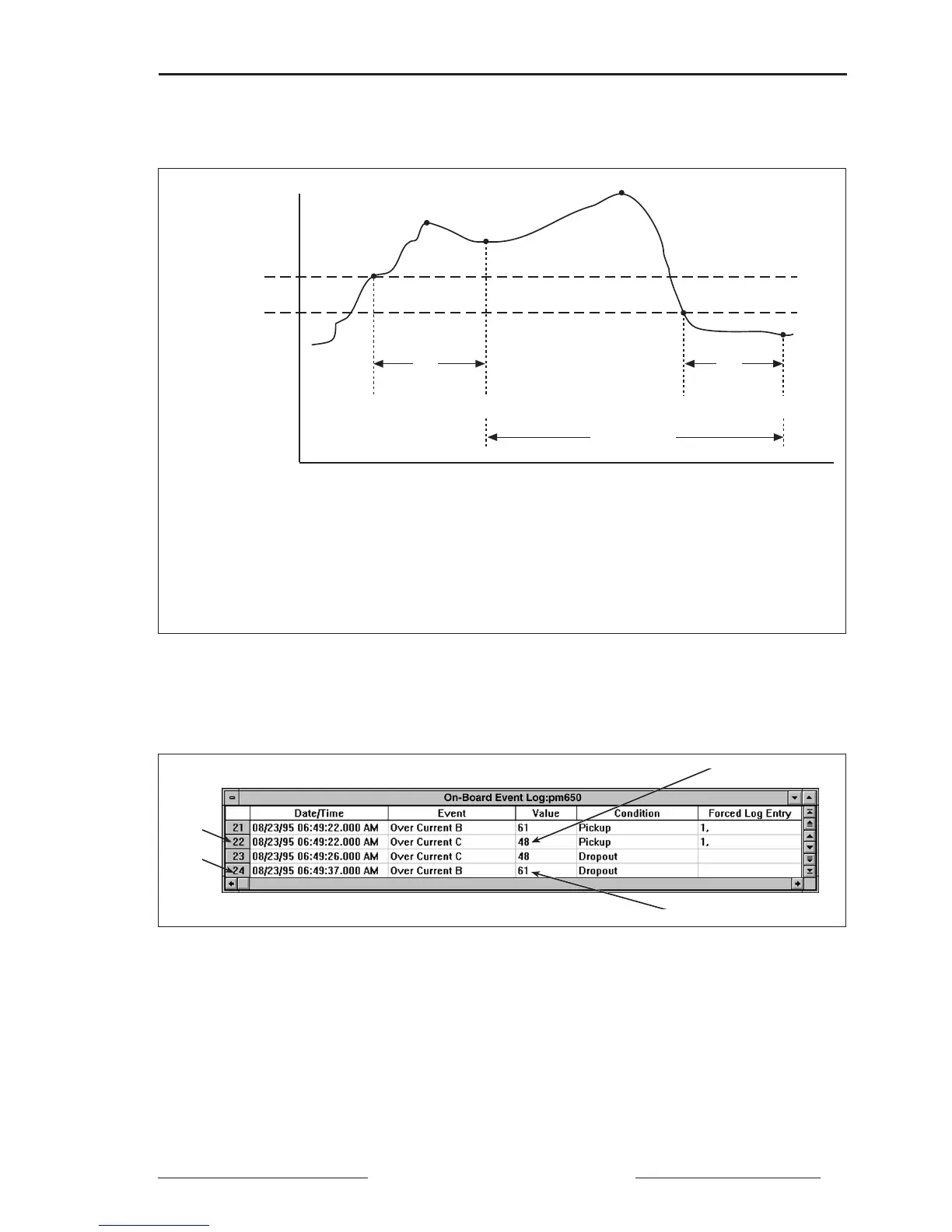
Figure 9-1 below illustrates how the power meter 650 handles setpoint-driven
alarms.
EV1 EV2
Max1
Max2
∆T
Pickup Delay
∆T
Dropout Delay
Pickup Setpoint
Dropout Setpoint
Alarm Period
Figure 9-1: How the power meter handles setpoint-driven alarms
EVI— Power meter 650 records the date/time that the pickup setpoint and time delay were satisfied, and
the maximum value reached (Max1) during the pickup delay period (∆T). Also, the power meter
performs any tasks—forced data log entries, relay output operations—assigned to the event.
EV2— Power meter 650 records the date/time dropout setpoint and time delay were satisfied, and the
maximum value reached (Max2) during the alarm period.
Figure 9-2 shows the event log entries for figure 9-1 displayed by
POWERLOGIC application software.
EV1
EV2
Max1
Max2
Figure 9-2: Sample event log entries
SETPOINT-CONTROLLED RELAY FUNCTIONS
The KYZ output can be used to operate an alarm horn or bell to annuciate
the alarm condition or as an input into a building management system.
For instructions on wiring the KYZ output as an alarm contact, see
Chapter 5—Wiring.