Power Meter Bulletin No. 3020IM9503R6/98
Chapter 6—Communications December 1998
42 1998 Square D All Rights Reserved
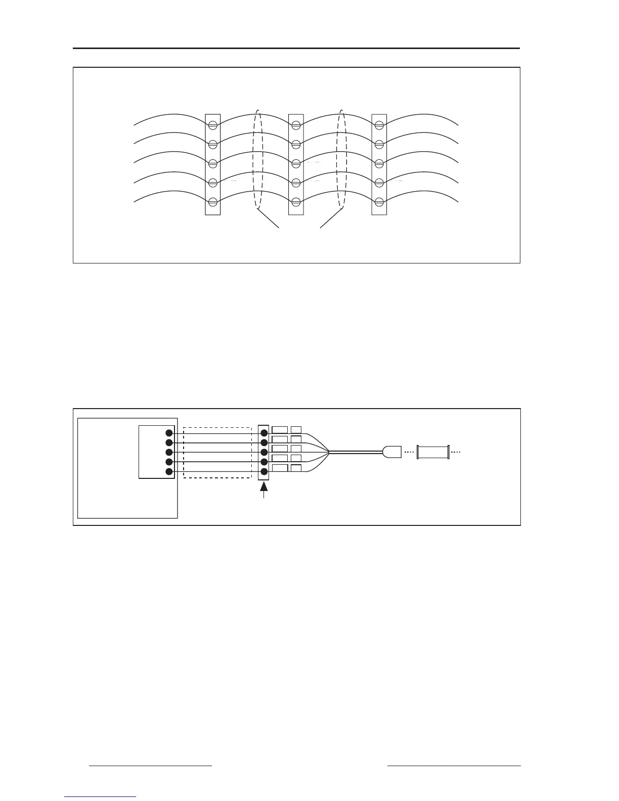
Figure 6-5: Daisychaining the RS-485 communications terminals
BIASING THE COMMUNICATIONS LINK (POWERLOGIC, MODBUS, OR JBUS)
For proper RS-485 communications performance, the communications link
must be biased (figure 6-6) using a POWERLOGIC Multipoint Communica-
tions Adapter (Class 3090 Type MCA-485). The adapter is placed between the
first device on the link and the communications port of a PNIM, SY/LINK
card, or other host device.
Figure 6-6: Connecting the power meter as the first
device on a PM&CS or Modbus communications link
To bias the communications link, refer to figure 6-6 and follow these steps:
1. Install the 5-position terminal block in a convenient location.
Note: The CAB-107 cable is 10 feet (3 m) long. If the terminal block must be
located farther than 10 feet from the host device, build a custom cable using Belden
8723 cable and a male DB-9 connector. See the CAB-107 pinout, page 74.
2. Plug the male end of the Multipoint Communications Adapter (MCA-485)
into the communications port of the PNIM, SY/LINK board, or other host
device.
Note: When connecting to a PNIM, connect the power meter to the top RS-422
port, labeled port 0. This port must be configured for POWERLOGIC mode.
IN+
IN-
OUT-
OUT+
SHLD
IN+
IN-
OUT-
OUT+
SHLD
IN+
IN-
OUT-
OUT+
SHLD
compa
e
ev
ce compa
e
ev
cecompa
e
ev
ce
To RS-485
Terminals of
Next Device
To RS-485
Terminals of
Next Device
Power Meter
or Other PM&CS-
Compatible, Modbus,
or Jbus Device
Belden 8723 (or equivalent) Comms Wire
(two twisted pairs with shield)
IN+
IN–
OUT+
OUT–
SHLD
IN+
IN–
OUT+
OUT–
SHLD
IN+
IN–
OUT+
OUT–
SHLD
➁
OUT–
➂
OUT+
➃
IN–
➄
IN+
➀
SHLD
21
20
22
23
24
IN+
SHLD
OUT–
OUT+
IN–
Green
Shield
Blue
Red
White
To Comm
Port of
Host Device
CAB-107
MCA-485
Belden 8723
RS-485
Terminals
Power Meter
5-Position
Terminal Block
Power Meter
or Other PM&CS-
Compatible, Modbus,
or Jbus Device
Power Meter
or Other PM&CS-
Compatible, Modbus,
or Jbus Device