Power Meter Bulletin No. 3020IM9503R6/98
Chapter 5—Wiring December 1998
30 1998 Square D All Rights Reserved
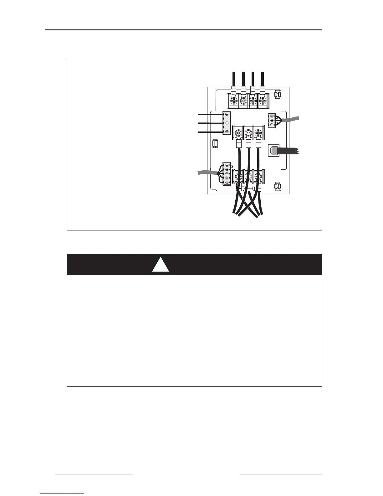
Typical power meter module wire routing is shown in figure 5-9 below.
Figure 5-9: Power meter wire routing
To wire the power meter, follow these steps:
1. Strip 0.25" (6 mm) of insulation from the end of all wires. Using a suitable
crimping tool, attach the spade connectors (in hardware kit) to the voltage
and current input wires (up to 12 AWG) as shown in figure 5-9.
HAZARD OF ELECTRICAL SHOCK, BURN, OR EXPLOSION.
• Before removing the terminal shield or making connections, turn off
all power supplying this equipment.
• Refer to the terminal identifications label on the terminal shield for
proper wiring polarities.
• Refer to page 22 for CPT and fuse recommendations.
• Snap terminal shield into closed position before turning power on.
Failure to observe these precautions will result in death or severe
personal injury!
DANGER
!
➃
➀ 3-Phase Voltage Inputs
➁ Control Power Terminals
➂ KYZ Output
➃ 3-Phase Current Inputs
➄ Communications Connection
to Display
➅ RS-485 Communications Terminals
➃
➁
➀
➂
➅
➄