UPS with Bypass Electrical Installation
26
Powerware
®
9170
+
UPS User’s Guide S Rev B www.powerware.com
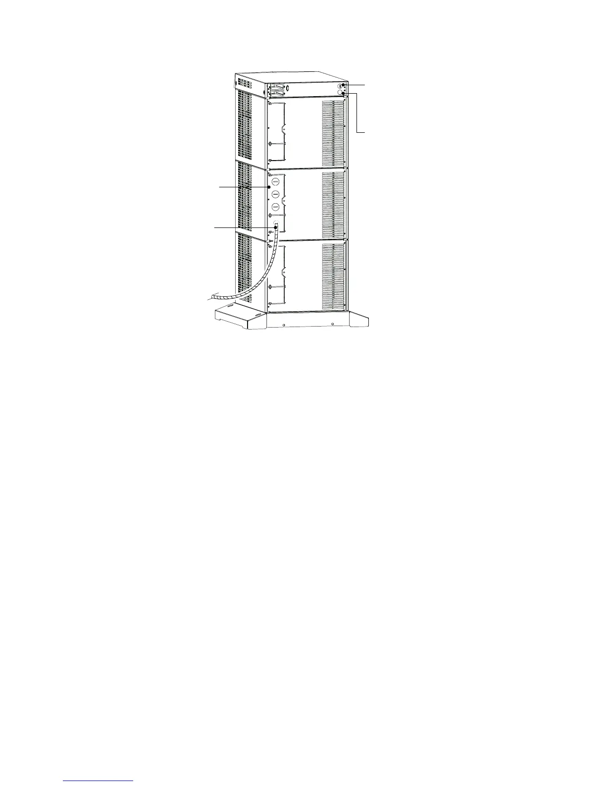
Entrance Panel
Battery Cable
Wiring Access Hole
for Optional EPO
and Bypass Input
Signals
Wiring Access Hole
for an Optional
Generator Input
Signal
Figure 15. UPS Power Entrance Panel (Nine -Slot Cabinet Shown)
3. Unscrew and remove the rear panel(s) of the UPS (top panel on
3- or 6-slot; top 2 panels on 9- and 12-slot). See Figure 15.
The entrance panel contains knockout openings for entrance
and exit conduits and for conduit to an optional external
battery cabinet. The entrance panel is located on the top 3-slot
section for 3- and 6 -slot cabinets; on the second section for 9-
and 12-slot cabinets as shown in Figure 15.
Wiring for optional emergency power-off (EPO) and bypass
input signals passes through the opening at the top back of the
cabinet. Wiring for an optional generator input signal must p ass
through a separate opening. Installing this wiring is described in
Steps 12 and 13 on page 31.
4. Remove the knockouts in the entrance panel for AC input and
AC output wiring.