UPS with Bypass Electrical Installation
29
Powerware
®
9170
+
UPS User’s Guide S Rev B www.powerware.com
CAUTION
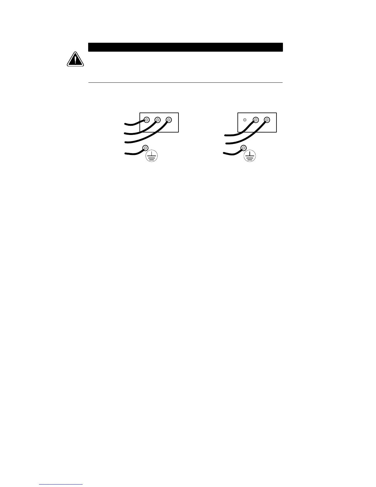
Confirm that the UPS is wired for the proper input voltage as shown in
Figure 18, and that the proper power modules (either split-phase or universal)
are installed to produce the desired output voltage. Do not mix the two types of
power modules in the same UPS cabinet.
(b) Universal Power Modules
(2-Wire P lus Ground Input)
200, 208, 220, 230, and 240 Vac
(a) Split-Phase Power Modules
(3-Wire Plus Ground Input) (2 PEN)
100/200, 110/220, 120/208, 120/240, 127/220 Vac
321321
L2
L1
N
GND
L1
L2/N
GND
Figure 18. UPS Input Wiring
9. For isolated output only. See Chapter 5, “Isolated Output
Wiring Diagrams” on page 51 to complete the wiring for isolated
output.
10. See the wiring diagrams beginning on page 32 which show
output configurations for various voltages and isolation options.
Make UPS output connections on the backplane board
terminating studs. Compression lugs (supplied in the accessory
kit) may be installed on the proper terminating studs. Wires may
also be terminated with ring terminals, which are attached to
the output terminating studs.
Figure 19 and Figure 20 describe output wiring configurations
for various output voltages. You must also set the operating
menu parameter 4-2-4 for the required output voltage as shown
in the wiring configuration dr awings.