UPS with Bypass Electrical Installation
30
Powerware
®
9170
+
UPS User’s Guide S Rev B www.powerware.com
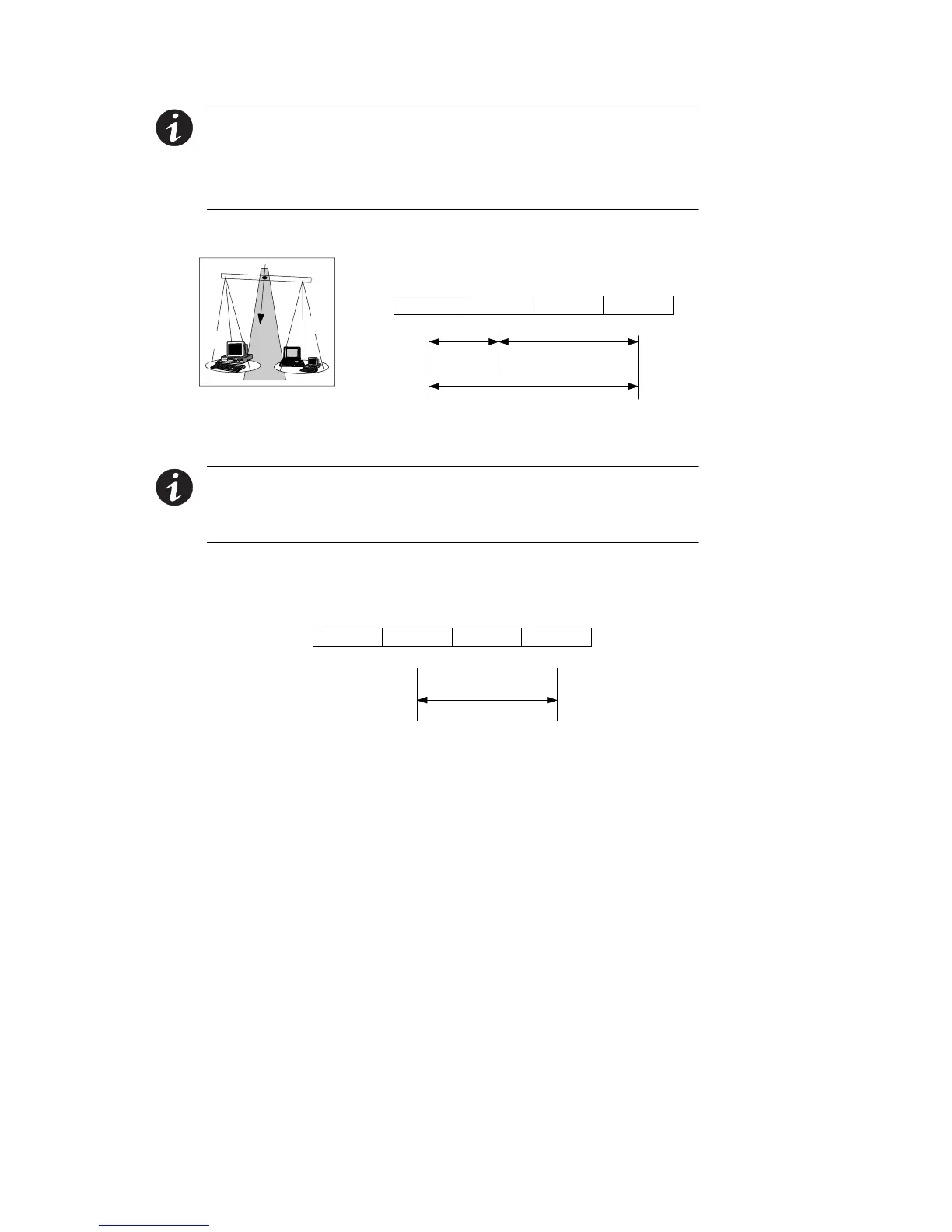
NOTE For Powerware 9170
+
UPS models with low -voltage hardwire
output, it is recommended to divide the total load as equally as possible
between X1 and X2, as shown in Figure 19.
NOTE Failure to balance the loads may cause an overload alarm even if
the full capacity of the UPS has not been reached.
N/-DC
50 or 60 Hz
100/200, 110/220, 127/220, 120/208, or 120/240V Out
Parameter 4-2-4 set to 200, 220, 208, or 240, as required.
X2 X1
XX
NL1
X
L2
100, 110, 127, or 120
50%
200, 220
208, or 240
100, 110, 127, or 120
50%
X1
X2
Figure 19. Split-Phase Power Modules with Non-Isolated Output
NOTE The factory-default wiring for all high-voltage receptacles in a
chassis without a power cord is 3 -wire plus ground input. If you have a
Universal Power Module (ASY-0674), all receptacles MUST be re-wired
for a 2-wire plus ground input configuration as shown in Figure 20.
N/-DC
50 or 60 Hz
200, 208, 220, 230, or 240V Out *
Parameter 4-2-4 set to 200, 208, 220, 230, or 240, as required.
X2 X1
XX
L2/NL1
*
Figure 20. Universal Power Modules with Non -Isolated Output
11. If the bypass switch is an MBB style, notice the cable routed out
oftheleftsideofthebypassswitchcabinet.Theredandblack
pair of wires (normally open) in this cable must be connected to
terminals 3 and 4 in Steps 12 and 13. (Do not connect the white
andblackpairofwiresinthiscable.)