UPS Electrical Installation
45
Powerware
®
9170
+
UPS User’s Guide S Rev B www.powerware.com
9. If any external hardwired control signals are required (EPO or
Generator On), unscrew and remove the top rear panel of the
cabinet and locate the terminal b lock (see Figure 31).
CAUTION
EPO circuits are not isolated from line voltage, and wiring must be installed
according to local codes using conduit or suitable primary supply cables.
The Generator On signal is isolated from line voltage and can be
treated as NEC Class 2 wiring.
Use 14–20 AWG, 600V wire (UL) or 14–26 AWG, 300V wire
(CSA) for all input control signals.
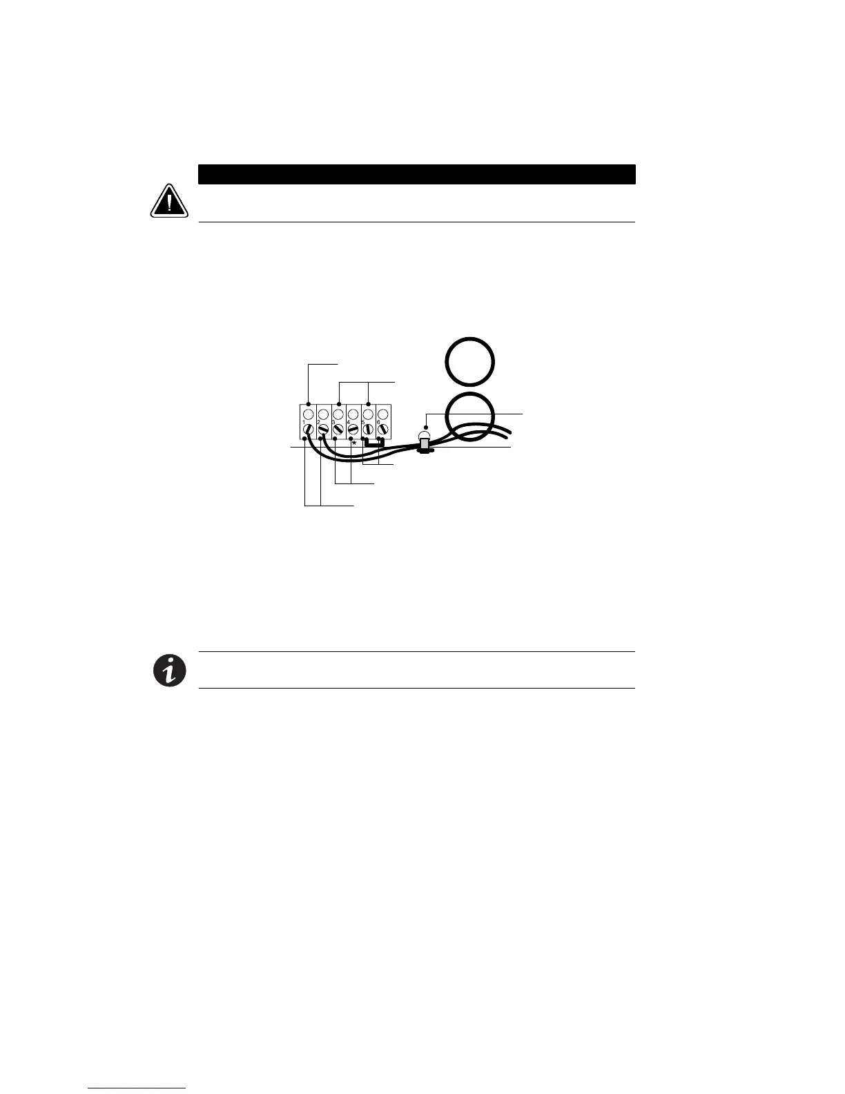
Generator On
(Normally Open)
Signal
Common
Emergency Power-Off (Normally Closed)
External Bypass *(Short to Common When Active)
Generator Set
Plastic Cable Tie
Figure 31. Input Control Signal Wiring
10. Place the signal wires through the proper conduit or grommet
above the terminal block and attach to appropriate terminals.
Secure each connection by torquing terminal screws to a
maximum 3.5 in lb (0.4 Nm). Provide strain relief for cables by
installing plastic cable ties.
NOTE Do not strain relieve EPO wiring with the same cable tie used for
Generator On wires.