Battery Cabinet Installation
58
Powerware
®
9170
+
UPS User’s Guide S Rev B www.powerware.com
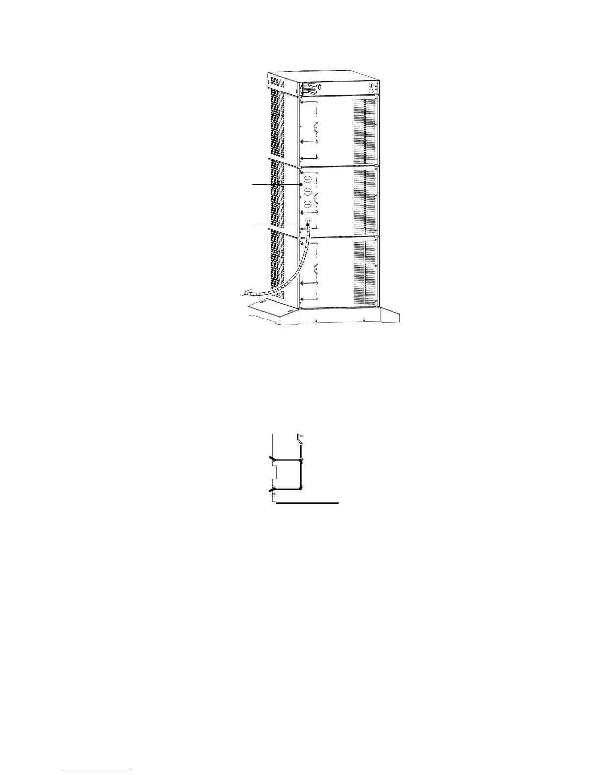
Entrance Panel
Battery Cable
Figure 42. UPS Power Entrance Panel
3. Use a pair of pliers to bend the narrow links (1 and 2 in
Figure 43) between the outer edge of the lower breakaway
panel and the rear panel.
4. Use the pliers to bend the entire breakaway panel (at 3 and 4 in
Figure 43) until it breaks away.
1
2
3
4
Figure 43. Breakaway Panel Links
5. Verify all hazardous voltages have been removed from the
backplane by testing with a voltmeter or other test device.