Battery Cabinet Installation
59
Powerware
®
9170
+
UPS User’s Guide S Rev B www.powerware.com
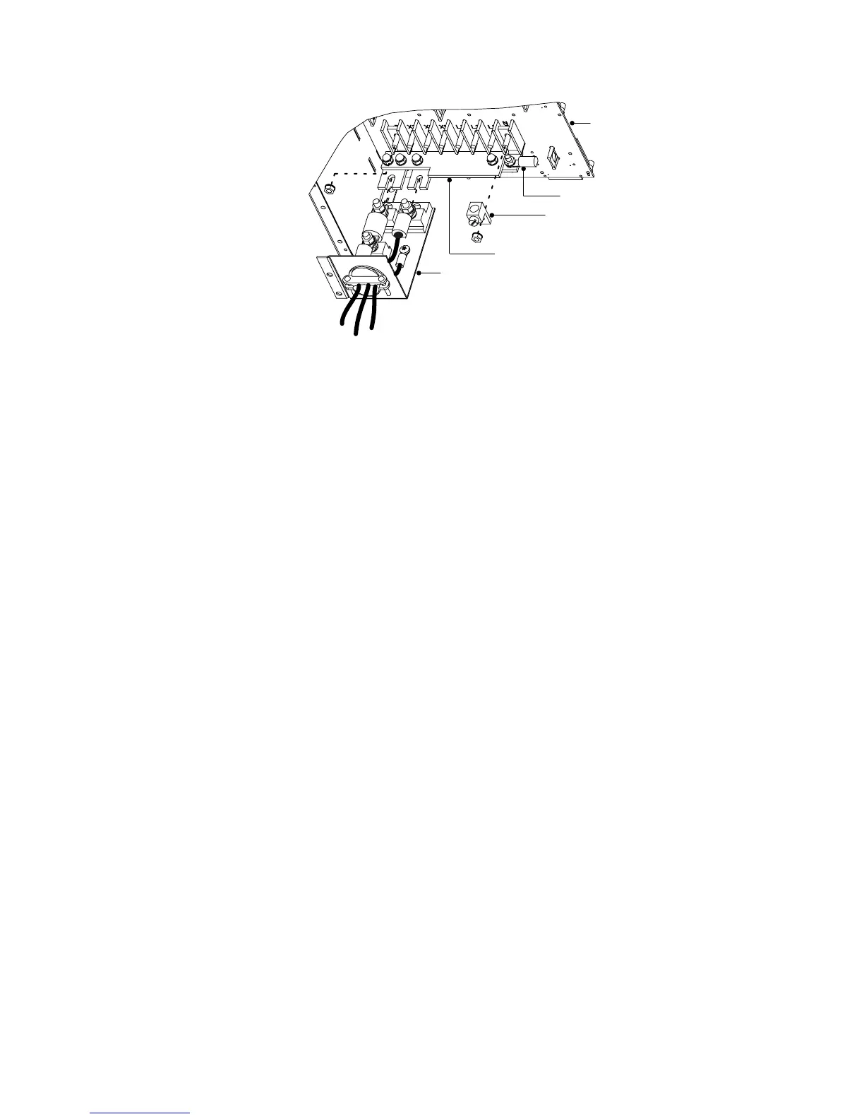
Cable Assembly
Backplane
Ring Terminal
Compression Lug
Bus-Bar Extension Assembly
Figure 44. Bus-Bar Extension Installation
6. Remove the nuts holding the +DC and the –DC bus bars to the
backplane as shown in Figure 44. Remove the ring terminal and
the compression lug from the –DC bolt.
7. Position the bus-bar extension assembly onto the +DC and –DC
bolts as s hown in Figure 44. Replace the compression lug onto
the –DC bolt of the bus-bar extension assembly. Secure the
assembly by replacing the two nuts removed in Step 6.
8. Use the bolt and nut supplied with the cable assembly to attach
the ring terminal to the empty hole in the –DC bus bar.
9. Torque all three bolts to 75–85 in lb (8.5–9.6 Nm).
10. Loosen the three large nuts on the end of the cable assembly
(see Figure 44).
11. Slip the terminals of the cable assembly onto the tabs of the
bus-bar extension, putting the tabs between the stud block and
the fuse end and between the other stud block and the cable
terminal.