UPS Startup
67
Powerware
®
9170
+
UPS User’s Guide S Rev B www.powerware.com
7. Plug the equipment to be protected into the UPS output
receptacles. Turn on the equipment that is connected to the
UPS.
DO NOT p rotect laser printers with the UPS because of the
exceptionally high power r equirements of the heating elements.
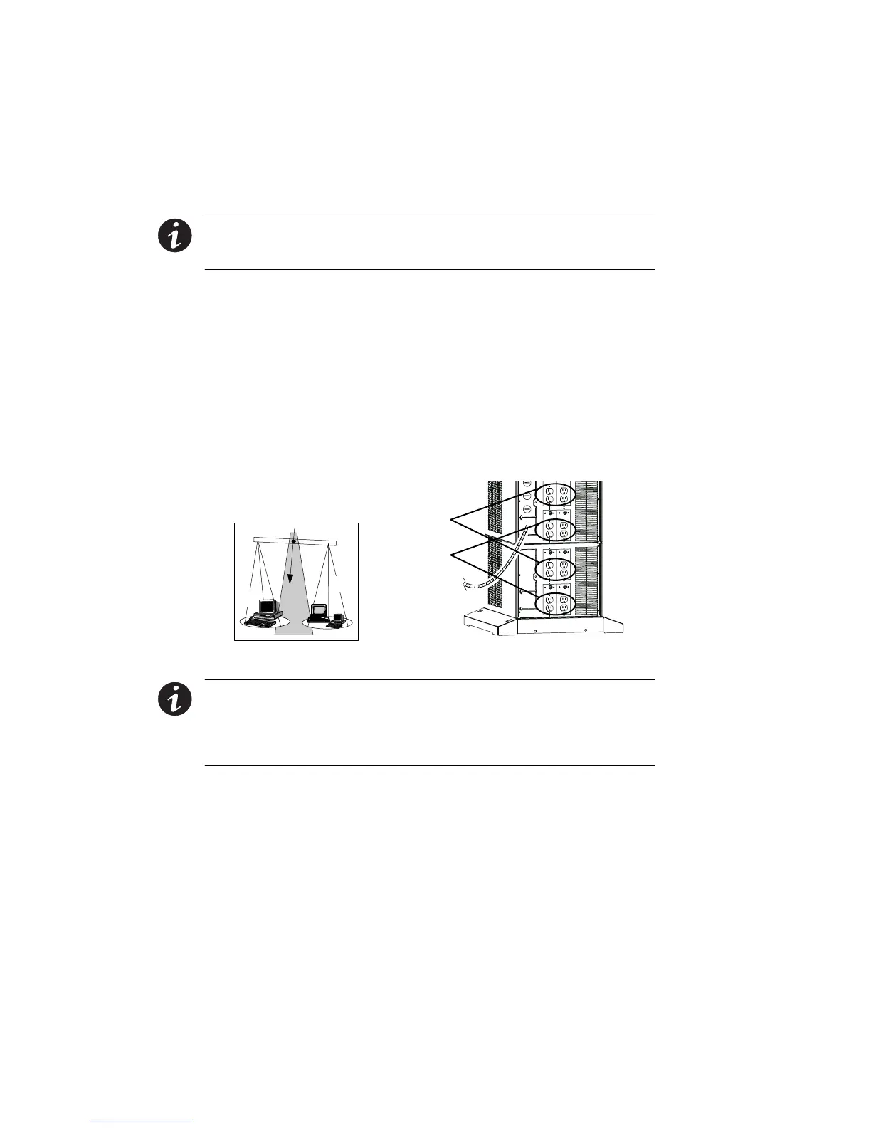
NOTE The total volt -ampere load must not exceed the volt-ampere rating
of the entire cabinet. Failure to balance the loads may cause an overload
alarm even if the full capacity of the UPS has not been reached.
For Powerware 9170
+
UPS models with low -voltage output
receptacles, it is recommended to divide loads between upper
and lower receptacles as equally as possible. (In some
configurations, each set of receptacles is limited to one half of
the total UPS capacity.) Whether the cabinet has one panel
containing eight receptacles, two panels containing
16 receptacles, or three panels containing 24 receptacles, you
should try to supply half of the UPS output through the upper
half of the receptacles (X1) and the other half through the
lowerhalfofthereceptacles(X2),asshowninFigure50.
X1
X2
X1
X2
Figure 50. Balancing Receptacle Loads
NOTE The factory-default wiring for all high-voltage receptacles in a
chassis without a power cord is 3 -wire plus ground input. If you have a
Universal Power Module (ASY-0674), all receptacles MUST be re-wired
for a 2-wire plus ground input configuration as shown in Figure 20 on
page 30.