Appendix V
100
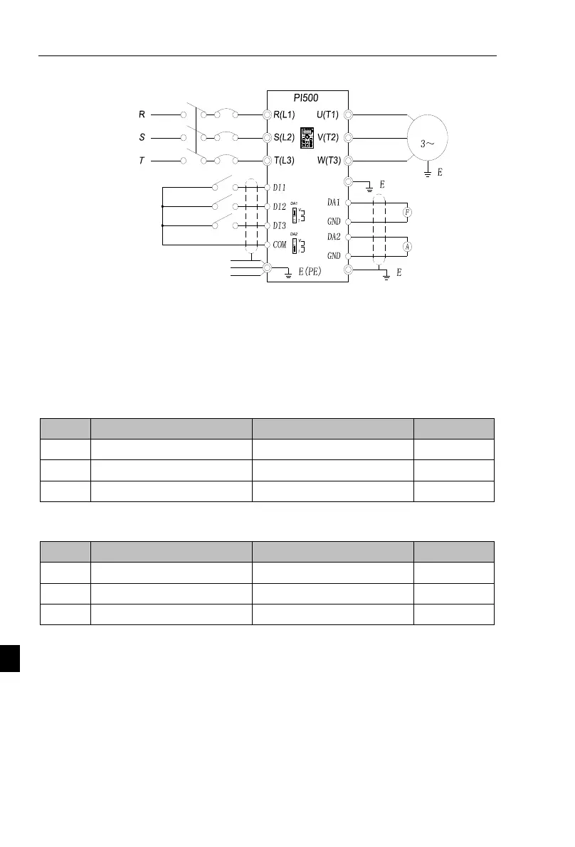
V-3-1 Electrical Diagram:
0~+10V DC
(Default)
0~+10V
Analog frequency meter
380V 50/60Hz
Three phase input power supply
Circuit breaker
Motor
M
%
M
FWD/STOP
REV/STOP
Fault reset
0~20mA DC
(Default)
External frequency meter and ammeter
4~20mA
Analog ampere meter
Standard default output: DA1 default 0 ~ 10V; DA2 default 4 ~ 20mA.
V-3-2 Connection:
The frequency meter is connected to the DA1 and GND terminals of the
inverter, and the ammeter is connected to the DA2 and GND terminals.
V-3-3 parameter setting:
When the system requires the drive DA1 0-5V signal output, you need to set the parameters as
follows:
DA1output function selection
DA1 zero bias coefficient
Note: DA1 jumper cap on drive control board needs to be shorted to V terminal.
When the system requires DA2 to provide 4-20mA signal output, the following parameters need
to be set:
DA2 output function selection
DA2 zero bias coefficient
Note: The DA2 jumper cap on the control board of the inverter needs to be shorted to I terminal.
V-4 Terminal block control forward /reverse running jog
V-4-1 electrical diagram:

 Loading...