Appendix V
105
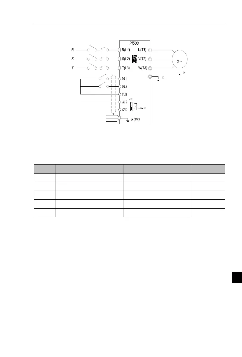
V-10-1 electrical diagram
(Default)
Circuit breaker
380V 50/60Hz
Three phase input power supply
Motor
M
%
FWD/STOP
REV/STOP
External simulation speed regulation
(external 0 ~ 20mA current signal given)
0 ~ 20mA analog signal
V-10-2 Connection:
Connect the (+) end of the external reference signal to the AI2 terminal, the
(-) end of the signal to the GND terminal of the inverter, and the AI2 jumper cap to the I terminal.
V-10-3 Parameter setting:
Frequency source master setting
AI2analog quantity setting
Terminal block control (LED on)
DI1 terminal function selection
DI2 terminal function selection
Note: If external 4 ~ 20mA current signal is given, please set F1.16 = 2.00V
.
V-11. Air compressor constant pressure control (sensor for
two-wire pressure transmitter)
V-11-1 electrical diagram:

 Loading...