EasyManuals Logo

Powtran PI500A Series User Manual

Powtran PI500A Series
112 pages
To Next Page IconTo Next Page
To Previous Page IconTo Previous Page
Page #26 background imageLoading...
Page #26 background image
Chapter 4 Installation and commissioning
22
Chapter 4
4-3-2.Function description of main circuit terminal
Terminal
Name
Explain
R
Inverter input terminals
Connect to three-phase power supply, single-phase
connects to R, T
S
T
Ground terminals
Connect to ground
P, RB
Braking resistor terminals
Connect to braking resistor
U
Output terminals
Connect to three-phase motor(Please do not connect single
phase motor)
V
W
+, -
DC bus output terminals
Connect to braking unit
P, +
DC reactor terminals
Connect to DC reactor(remove the shorting block)
4-4.Control circuit terminals
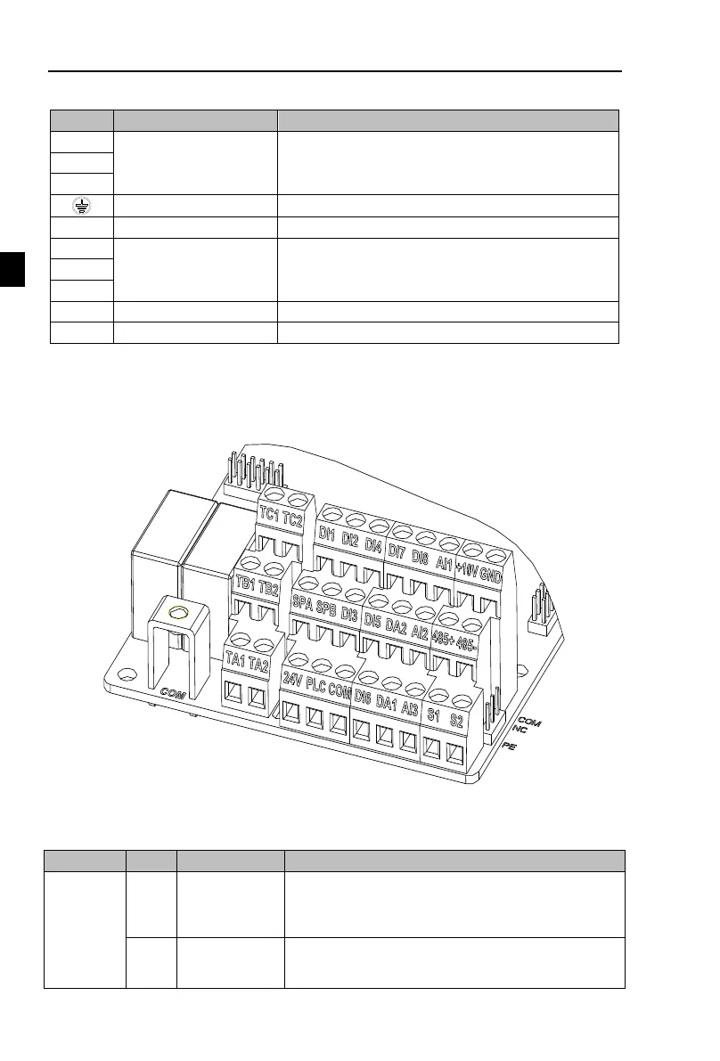
4-4-1.Control circuit terminals arrangement
1. Control panel control circuit terminals
Figure 4-15Control panel control circuit terminals
4-4-2.Description of control circuit terminals
Category
Symbol
Name
Function
Power
supply
+10V-
GND
10V power
supply
Output +10V power supply, maximum output current:
10mA
Generally it is used as power supply of external
potentiometer, potentiometer resistance range: 1 to 5kΩ
+24V-
COM
+24V power
supply
Output +24V power supply, generally it is used as power
supply of digital input and output terminals and external
sensor.

Table of Contents

Other manuals for Powtran PI500A Series

Questions and Answers:

Question and Answer IconNeed help?

Do you have a question about the Powtran PI500A Series and is the answer not in the manual?

Powtran PI500A Series Specifications

General IconGeneral
BrandPowtran
ModelPI500A Series
CategoryDC Drives
LanguageEnglish

Related product manuals