Basic Hardware Components PPT VISION, Inc.
3-12 A-Series Hardware Guide
RLD3 LED Ringlight Specifications
This table lists the power and trigger specifications for the ringlight.
Power Input Voltage 24 VDC
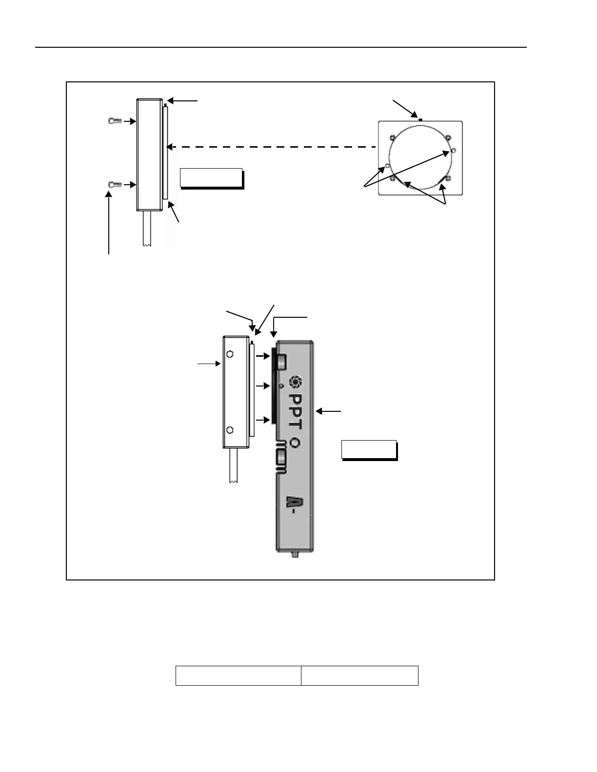
Adapter Mounting Holes
3M x 6mm (x 2)
Countersunk side out
Side
2. Mount the adapter to
the ringlight and tighten
the mounting screws.
RLD3 LED ringlight
Side View
Figure 2
1. Loosen the set screw
A-Series Camera
Adapter
Adapter Mounting
Ring
3.Slide the adapter and ring-
light over the adapter mount-
ing ring on the camera
Retaining flanges**
4.Be sure the retaining
flanges** on the adapter are
centered in the mounting ring
groove
5.Gently tighten the set screw*
until the adapter is firmly attached
to the camera. Do not overtighten
Set Screw*
Rear of ringlight
Adapter - Counter-
sunk side out
Mounting Screws (insert
through front of ringlight body)