Cable Reference PPT VISION, Inc.
5-8 A-Series Hardware Guide
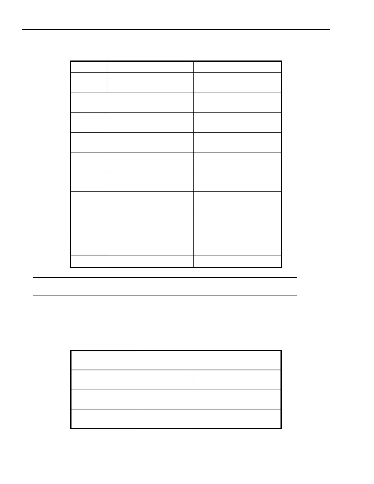
Complete this worksheet to document A-Series I/O wiring connections for the Terminal Block (except A10). See “Unter-
minated I/O Cable (except A10)” on page 5-8 for details about connecting the optional Unterminated I/O cable.
*IMPORTANT NOTE: The power connection terminal numbers for the Terminal Block and the Unterminated cable wire
numbers are not the same. Use caution when connecting power.
Unterminated I/O Cable (except A10)
If you use the optional unterminated I/O cable (PPT Part # 606-0644-xx), refer to this wire color table to connect the
unterminated end of the cable to the controlled devices.
Terminal # Signal Name External Signal Description
1
2
Trigger Input +
Trigger Input -
3
4
Input 1 and Shift Event+
Input 1 and Shift Event -
5
6
Input 2 and Event Input +
Input 2 and Event Input -
7
8
Strobe Output +
Strobe Output -
9
10
Output 1 +
Output 1 -
11
12
Output 2 +
Output 2 -
13
14
Output 3 +
Output 3 -
15
16
Output 4 +
Output 4 -
17 24 VDC Power + (See Note*)
18 24 VDC Power -
19 24 VDC Power Ground
Micro D Sub
Connector Pin
Wire Color Signal Name
1
2
White/Brown
Brown/White
Trigger Input +
Trigger Input -
3
4
White/Orange
Orange/White
Input 1 and Shift Event+
Input 1 and Shift Event -
5
6
White/Yellow
Yellow/White
Input 2 and Event Input +
Input 2 and Event Input -