I/O Reference PPT VISION, Inc.
4-2 A-Series Hardware Guide
This table lists the connector/terminal number input signals for the A-Series model (except A10). See page 5-7 for more
details.
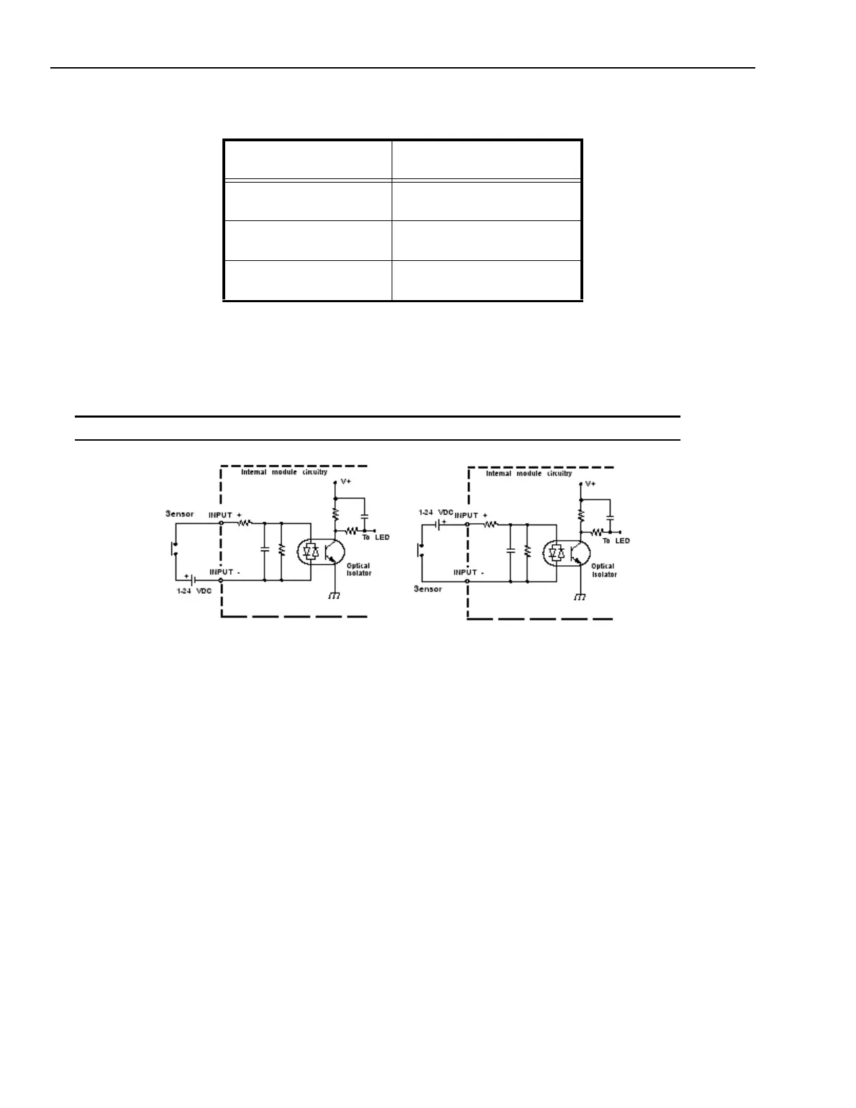
Sample Wiring Diagram
The diagram below shows a common way to wire an input.
Note: All connections to inputs must be made using properly grounded shielded cable.
Connector and terminal
block number
Signal Name
1
2
Trigger Input +
Trigger Input -
3
4
Input 1 and Shift Event+
Input 1 and Shift Event -
5
6
Input 2 and Event Input +
Input 2 and Event Input -
Configuration shown is
sensor current sourcing
Configuration shown is
sensor current sinking