Basic Hardware Components PPT VISION, Inc.
3-14 A-Series Hardware Guide
Power Supply
Warning: To avoid electrical shock, disconnect all power to the power supply before working on it.
Avertissement: Pour éviter le choc électrique, débranchez toute la puissance à l'alimentation d'énergie avant de tra-
vailler à lui.
This section provides a basic description of the optional power supply wiring for the PPT A-Series camera. Power is con-
nected to the camera through the A-Series Terminal block (see “I/O Terminal Block” on page 5-2) or the unterminated
cable (see “Unterminated I/O Cable (A10 Only)” on page 5-4).
IMPORTANT NOTE: The ground terminal on the camera’s +24V power input (terminal block #19 or unterminated
cable pin # 21) must be connected to the power supply’s grounded chassis/enclosure. This connection is needed to insure
electromagnetic compliance and proper operation.
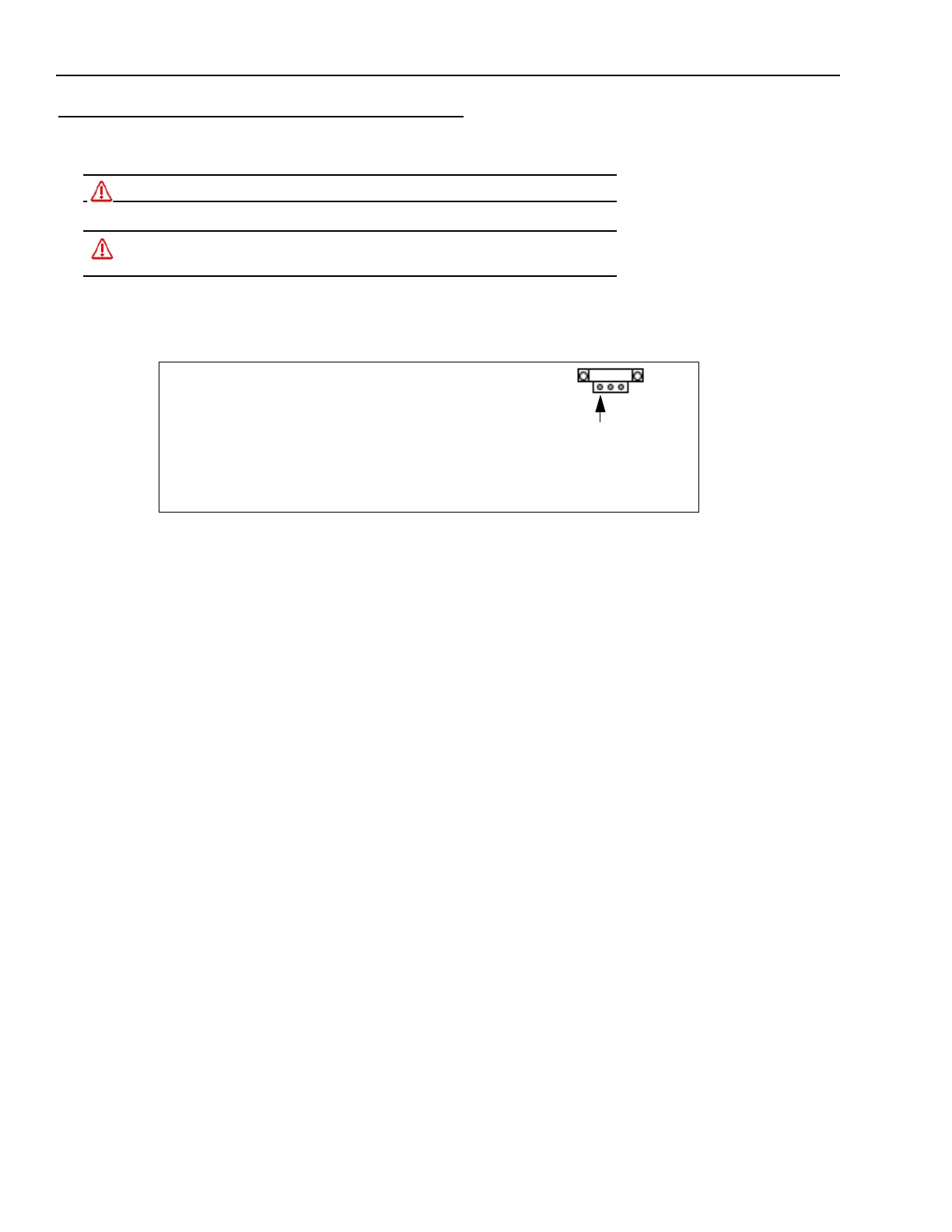
Pin 1
Power Connector
PPT Part # 244-0408
(Screw Terminal Side)
Power Connector
Pin 1 24VDC Supply Output Plus
Pin 2 24VDC Supply Output Minus or Ground
Pin 3 Power Supply Circuit Ground