PPT VISION, Inc. Basic Hardware Components
A-Series Hardware Guide
3-13
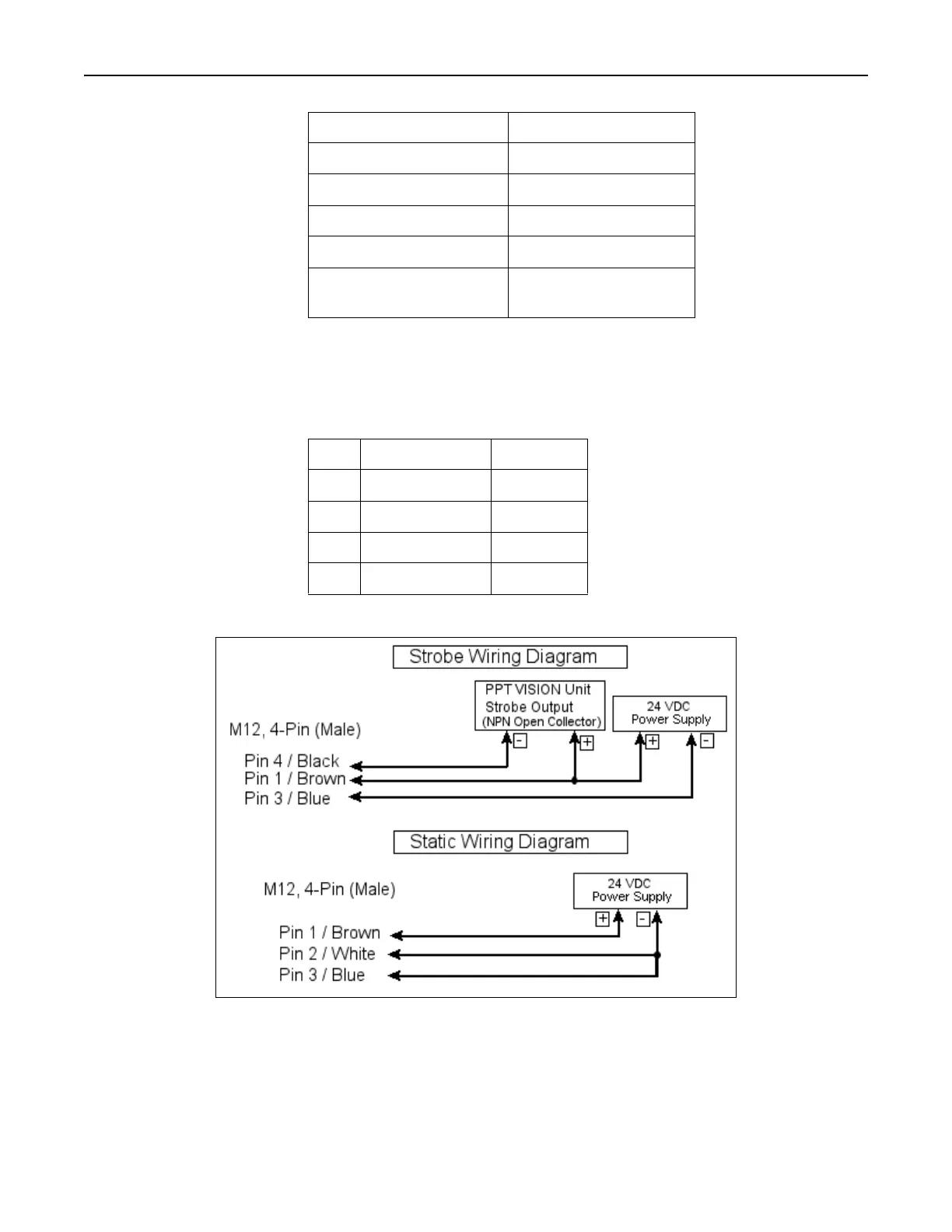
RLD3 LED Ringlight Wiring
The ringlight cable connector pinout is shown in this table.
These diagrams show how to connect the RLD3 LED ringlight for static or strobe mode.
Power Input Current 0.5 Amps Max
Trigger Input Voltage 0-26 VDC
Trigger Turn-On Voltage >3.3 VDC
Trigger Turn-Off Voltage <1.5 VDC
Trigger Input Pulse Width 25 - 500 microseconds
Maximum Trigger Rate 0 - 60 HZ, (3% duty
cycle)
Pin Signal Wire Color
1+24 VDC Brown
2NPN Strobe White
3Ground Blue
4 PNP Strobe Black