Cable Reference PPT VISION, Inc.
5-10 A-Series Hardware Guide
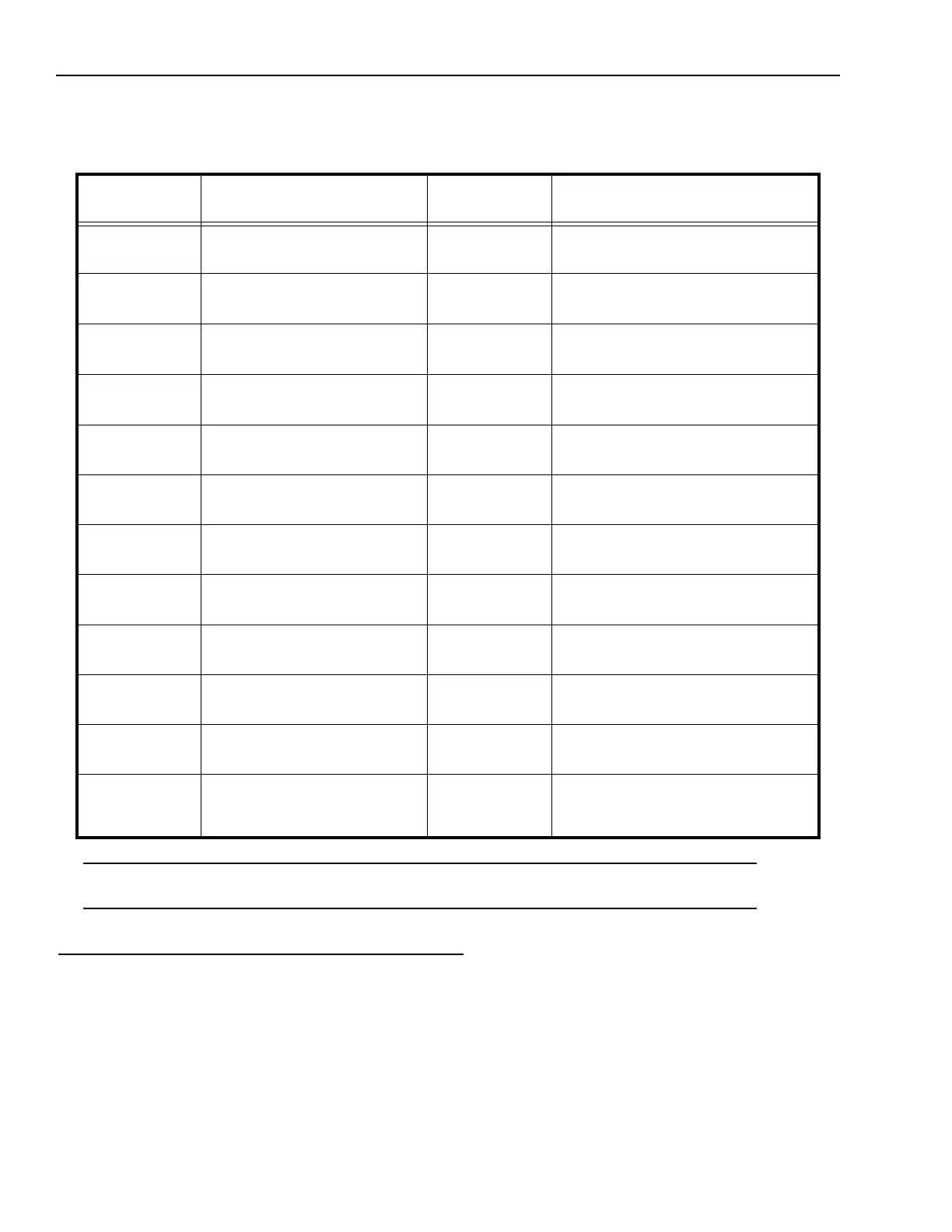
Complete this worksheet to document A-Series I/O wiring connections for the optional Unterminated I/O cable (except
A10). See “Terminal Block Connection Table (except A10)” on page 5-7 for details about connecting the optional Termi-
nal Block.
*IMPORTANT NOTE: The power connection terminal numbers for the Terminal Block and the Unterminated cable wire
numbers are not the same. Use caution when connecting power.
Strobe
The strobe output signal is provided on pins 7 and 8 of the camera’s I/O connector. These pins provide optically isolated,
current-mode signals (300mA maximum continuous DC current at 20° C (68° F) – derated at higher temperatures).
Micro D Sub
Connector Pin
Signal Name Wire Color External Signal Description
1
2
Trigger Input +
Trigger Input -
White/Brown
Brown/White
3
4
Input 1 and Shift Event+
Input 1 and Shift Event -
White/Orange
Orange/White
5
6
Input 2 and Event Input +
Input 2 and Event Input -
White/Yellow
Yellow/White
7
8
Strobe Output +
Strobe Output -
White/Green
Green/White
9
10
Output 1 +
Output 1 -
White/Blue
Blue/White
11
12
Output 2 +
Output 2 -
White/Violet
Violet/White
13
14
Output 3 +
Output 3 -
White/Grey
Grey/White
15
16
Output 4 +
Output 4 -
White/Pink
Pink/White
17
18
24 VDC Power + (See Note*)
24 VDC Power +
White/Tan
Tan/White
19
20
24 VDC Power -
24 VDC Power -
Tan/Brown
Brown/Tan
21
22
24 VDC Power Ground
24 VDC Power Ground
Tan/Orange
Orange/Tan
23
24
25
Serial Transmit
Serial Receive
Serial Ground
Tan/Yellow
Yellow/Tan
Tan/Pink