A-Series Hardware Guide 5-1
CHAPTER 5
Cable Reference
This section provides details of the cables used with the A-Series camera. Both cables are connected to the camera’s bot-
tom.
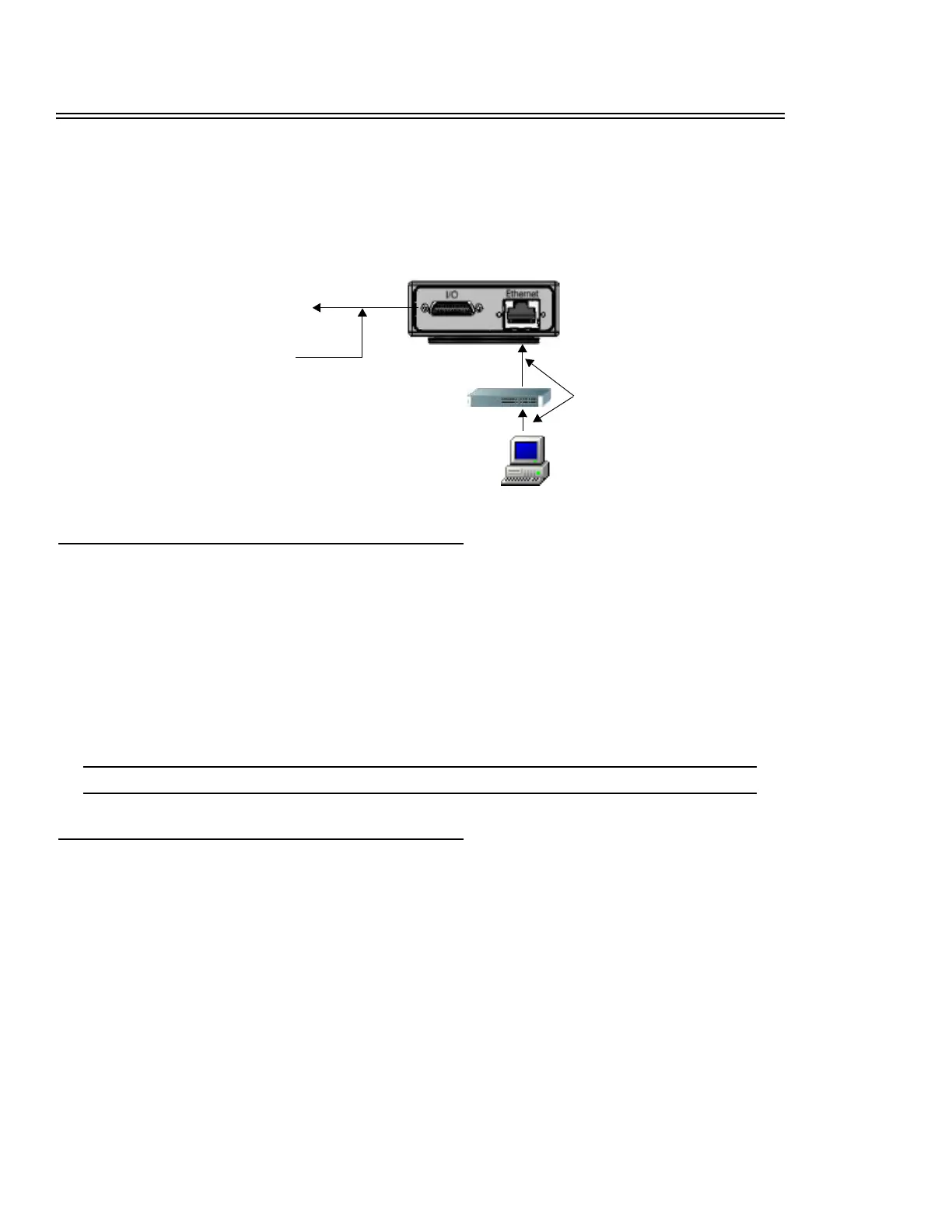
Ethernet
An optional screw-down Ethernet cable (PPT Part # 606-0619-xx) or optional standard double-shielded Ethernet cable
(PPT Part # 606-0615-xx) is used to connect the PPT A-Series camera to the client computer. (The last two digits of the
part number indicate the cable length in feet.) PPT recommends you use at least Cat5e Ethernet cable to connect the client
and the A-Series camera. Two cables will be needed; one from the A-Series to the switch and one from the switch to the
client PC.
A crossover cable is not needed because the camera is auto-negotiating; it can tell the difference between a peer-to-peer
connection and a router/switch connection and configures itself to suit the environment.
NOTE: Use only a switch or a router between the client and the A-Series camera. Do not use a hub.
Input/Output
To connect the camera I/O to external control devices, use the optional terminated I/O cable with the I/O terminal block
(page 5-2), or the optional unterminated I/O cable (page 5-4 or page 5-8).
Terminated I/O Cable
This cable connects the camera to the I/O terminal block. It has a 25-pin Micro D Sub male connector on the camera end
and a 25-pin high density male connector on the terminal block end. (PPT Part # 606-0607-xx) The final two digits of the
cable part number indicate the cable length in meters.
Optional I/O Cable
See page 5-1 for details
Client computer
or network
Optional Ethernet Cable
See page 5-1 for details
To optional A-Series I/O
Terminal Block
Optional
Ethernet switch