Loop Leader PD6600 Series Loop-Powered Meters Instruction Manual
12
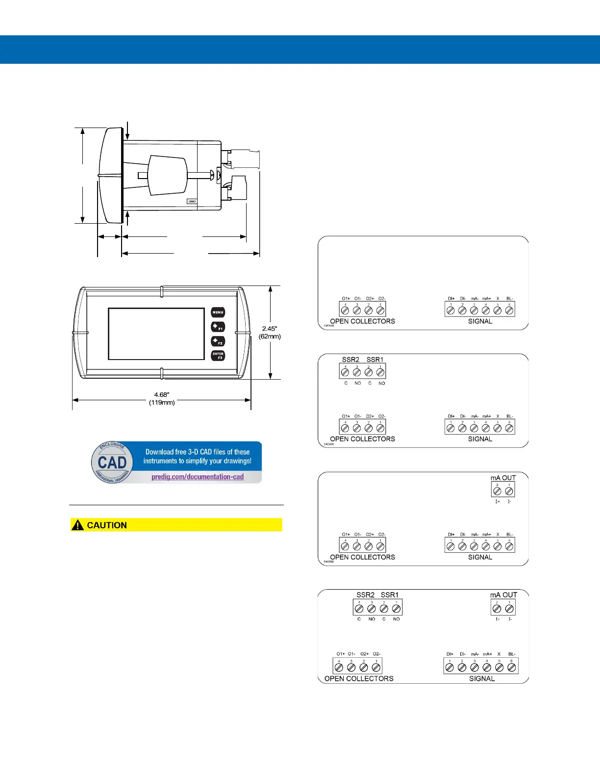
Dimensions
All units: inches (mm)
Figure 3. Meter Dimensions - Side View
Figure 4. Meter Dimensions - Front View
• Use copper wire with 60°C or 60/75°C insulation
for all line voltage connections. Observe all safety
regulations. Electrical wiring should be performed
in accordance with all applicable national, state,
and local codes to prevent damage to the meter
and ensure personnel safety.
Connections
All connections are made to removable screw
terminal connectors located at the rear of the meter.
This section is only intended for PD6602 and PD6604
safe area installations.
PD6606 and PD6608 installation must be performed in
accordance with Control Drawing LIM6600-2 in order to
meet agency approval ratings.
Connectors Labeling
The connectors’ label, affixed to the meter, shows the
location of all connectors available with requested
configuration.
Figure 5. PD660#-LNN Connector Label
Figure 6. PD660#-L2N Connector Label
Figure 7. PD660#-L3N Connector Label
Figure 8. PD660#-L5N Connector Label
(45mm)
0.59"
3.2"
(81mm)
2.45"
3.6"
 Loading...