Loop Leader PD6600 Series Loop-Powered Meters Instruction Manual
38
Meter Operation
The meter is capable of accepting a 4-20 mA current
signal and displaying it in engineering units from
-9999 to 99999 on the top line or from -9,999,999 to
99,999,999 (with commas, if desired) on the bottom
line. For example, a 4-20 mA signal could be dis-
played as -50.00 to 50.00.
The dual-line display can be customized to display the
process variable and other parameters in a wide vari-
ety of ways. Typically, the top line is used for the pro-
cess variable while the bottom line is used for engi-
neering units, custom tag, or process variable per-
centage of full scale.
The 4-20 mA input can be scaled to display the pro-
cess in two different scales; for example: with PV2
enabled, the top display could indicate level in feet
and the bottom display could indicate the volume in
gallons.
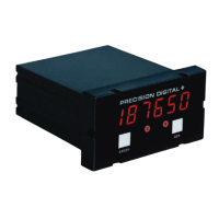
Front Panel Buttons Operation
Press to enter or exit
Programming Mode, view
settings, or exit max/min
readings
Press to display max/min
readings or other
parameter/function
assigned through the
User menu
Press to reset max/min
readings or other
parameter/function
assigned through the
User menu
Press to acknowledge
alarms or other
parameters/function
assigned through the
User menu
Function Keys Operation
During operation, the programmable function keys
operate according to the way they have been pro-
grammed in the Advanced Features – User menu.
The table under Front Panel Buttons Operation shows
the factory default settings for F1, F2, and F3.
A hint message may be enabled in order to provide a
description of what each function key does prior to
executing their assigned function. See Enabling the
Function Key Hint Feature (HINT) on page 36.
Digital Input Operation
A digital input is standard on the meter. This digital
input is programmed identically to function keys F1,
F2, and F3. The input is triggered with a contact clo-
sure between DI+ and DI-, or with an active low sig-
nal. During operation, the digital input operates ac-
cording to the way it has been programmed in the
Advanced Features – User menu.
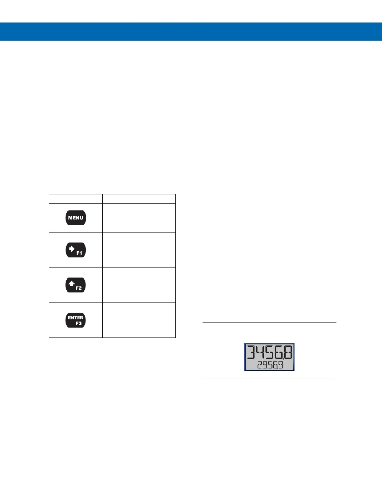
Maximum/Minimum Readings
The max & min readings (peak & valley) reached by
the process can be displayed either continuously or
momentarily.
Display momentarily by pressing the F1 key (default)
or assigning to any of the other function keys or to the
digital input in the User menu.
Display continuously by pressing the Enter button
while the max/min is being displayed to lock the dis-
play. Press Enter again to unlock.
Any of the F1-F3 function keys (buttons) and the digi-
tal input can be programmed to reset the max & min
readings. The meters are set at the factory to display
the max reading by pressing the Right Arrow/F1 but-
ton and to use the Up-Arrow/F2 button to access the
Reset menu. Press the Right Arrow button to cycle
through the available parameters to reset.
Top Line: Maximum Value
Bottom Line: Process Value
 Loading...