Loop Leader PD6600 Series Loop-Powered Meters Instruction Manual
29
Stopwatch (STPWATCH)
The stopwatch function may be used to manually run
and control a process for a specific time interval up to
99 hrs., 59 min, and 59 seconds. The stopwatch func-
tion may be assigned to any relay. There are three
settings needed to use the function effectively.
4. Assign stopwatch to either top or bottom dis-
play line
5. Assign the relay to control the process
(on/off)
6. Assign a function key or digital input to
start/stop the stopwatch
Application Example
In order to maintain consistency of a product, it is
necessary to take and test samples at different times
throughout the day. The stopwatch function is used to
open and close a solenoid valve to know the exact
amount of time needed to complete the desired sam-
ple. Once this is determined, the timer function can be
used to automatically take a sample (batch) based on
the time determined using the stopwatch function.
Setup: Assign the following to Stopwatch Function
• Bottom display line
• Relay 1
• F3: Start/Stop
Procedure
• Press F3 to start the stopwatch; relay 1 turns
on and the process starts running.
• Press F3 to stop the stopwatch; relay 1 turns
off and the process stops.
• The bottom display indicates the time it took
to complete the sample.
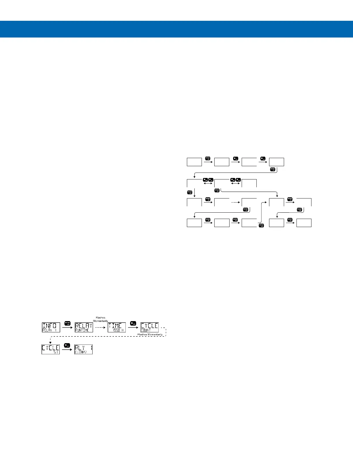
Runtime & Cycle Count (INFO)
The relay information menu shows runtimes and cycle
counts for each relay. These values may be cleared
at any time by selecting the Clear option (CLEAR?).
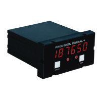
Isolated 4-20 mA Output (4-20 mA)
The 4-20 mA menu is used to scale the isolated 4-20
mA output based on display values. This menu is not
present on models without a 4-20 mA output option.
The 4-20 mA analog output can be scaled to provide
a 4-20 mA signal for any PV display range or to
simply retransmit the 4-20 mA input. The output may
be disabled (DISABLE), and will only output the
minimum signal.
Overrange and underrange values determine what
mA signal the meter will output if the mA input is
underrange (<3.5 mA) or overrange (>20.5 mA). This
value may be set to 1 mA, 3.5 mA, 3.8 mA, 20.5 mA,
20.8 mA, 23 mA, or disabled.
No equipment is needed to scale the analog output;
simply program two display values and corresponding
mA output signals.
Process Variable (PV)
To scale the analog output, enter display value 1 and
a corresponding analog output value for this display,
and enter display value 2 and a corresponding analog
output value for this display value. This will provide a
scaled linear analog output.
Retransmit (RETRANS)
This option will retransmit the 4-20 mA analog input
without the need to scale the output.
Output Manual Control (CONTROL)
The Control menu is used to control the open collec-
tor outputs, 4-20 mA analog output, and the relays
manually, ignoring the input. Each open collector,
relay, and analog output can be programmed inde-
pendently for manual control. Selecting automatic
control sets all relays and analog output for automatic
operation.
After selecting manual control for a specific output,
you can set the output value. To change the output
value, return to the Control menu, select the output to
control, select manual control, and enter a new input.
SETUP
OUTPUT
OPEN
COLLECTR
OUT
RELAY
OUT
4-20 mA
4-20
PV
4-20
RETRANS
4-20
DISABLE
DSP 1
+00,000.00
DSP 1
GAL
Flashes
Units
OUT 1
04.000
DSP 2
+00,100.00
OUT 2
20.000
AOUT
UNDER
U-RNG
DISABLE
AOUT
OVER
O-RNG
DISABLE
AOUT
SCALE
 Loading...