Loop Leader PD6600 Series Loop-Powered Meters Instruction Manual
33
Advanced Scaling and Calibration
(
SCALE.CAL)
This menu offers options to scale or calibrate the
meter.
Scaling the Input (SCALE)
The scale menu in the Advanced menu is the same
as the scale menu in the Input menu. See Scaling the
4-20 mA Input (SCALE) on page 19 for details about
scaling the meter.
Calibrating the Input (CAL)
To scale the meter without a signal source, refer to
Scaling the 4-20 mA Input (SCALE), page 19.
The meter can be calibrated to display the process in
engineering units by applying the appropriate input
signal and following the calibration procedure. The
CAL menu can be used either with a calibrated
current source or with a live signal coming from a
4-20 mA transmitter connected to the process being
measured.
During calibration, the mA input value will be
displayed as INP 1 and INP 2. Adjust the input
source until the desired mA value is shown.
The use of a calibrated signal source is required.
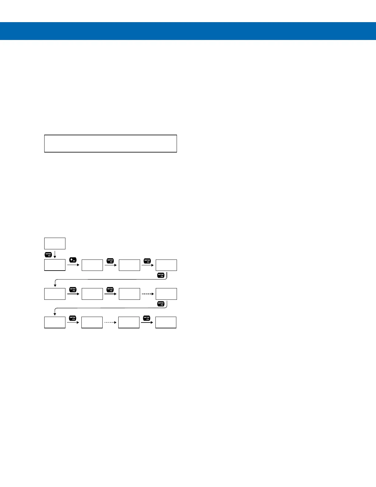
Follow these steps to calibrate the input:
1. After accessing the SCALE.CAL menu, press
the Right-Arrow button to scroll to the
Calibration menu (CAL PV) and press Enter.
2. Select the appropriate units for the desired
process variable, then press Enter. For
information on units, see Available Unit
Classes and Units on page 20.
3. The meter displays INP 1. Apply a known
signal and press Enter. The display will flash
while accepting the signal.
4. After the signal is accepted, the meter displays
DSP 1. Enter a corresponding display value
for the signal input, and press Enter to accept.
5. The meter displays INP 2. Apply a known
signal and press Enter. The display will flash
while accepting the signal.
6. After the signal is accepted, the meter displays
DSP 2. Enter a corresponding display value
for the signal input and press Enter to accept.
7. After completing calibration, the SAVE? display
will need to be acknowledged using the Enter
key before calibration will take effect.
Low-Flow Cutoff (CUTOFF)
The low-flow cutoff feature allows the meter to be
programmed so that the often-unsteady output from a
differential pressure transmitter at low flow rates al-
ways displays zero on the meter.
The cutoff value may be programmed from 0 to
999999.9. The meter will display zero below the cutoff
value. The cutoff may also be disabled to display
negative values.
PV
SCALE.CAL
CAL
UNITS
UNITS
VOLUME
UNIT
GAL
DSP 1
GAL
Flashes
Units
SCALE
PV
CAL
PV
INP 1
04.000 mA
DSP 1
+00,000.00
DSP 2
GAL
Flashes
Units
INP 2
20.000 mA
DSP 2
+00,100.00
SAVE?
 Loading...