Brake Caliper Assembly Replacement
About
This procedure provides instruction to remove and install the Brake Caliper assembly.
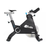
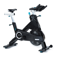
There are separate replacement procedures, one for the Spinner® Chrono
1
™ Power and
one for the Spinner® Climb™ models.
Brake Caliper replacement requires removal of the flywheel, drive belt, and generator belt.
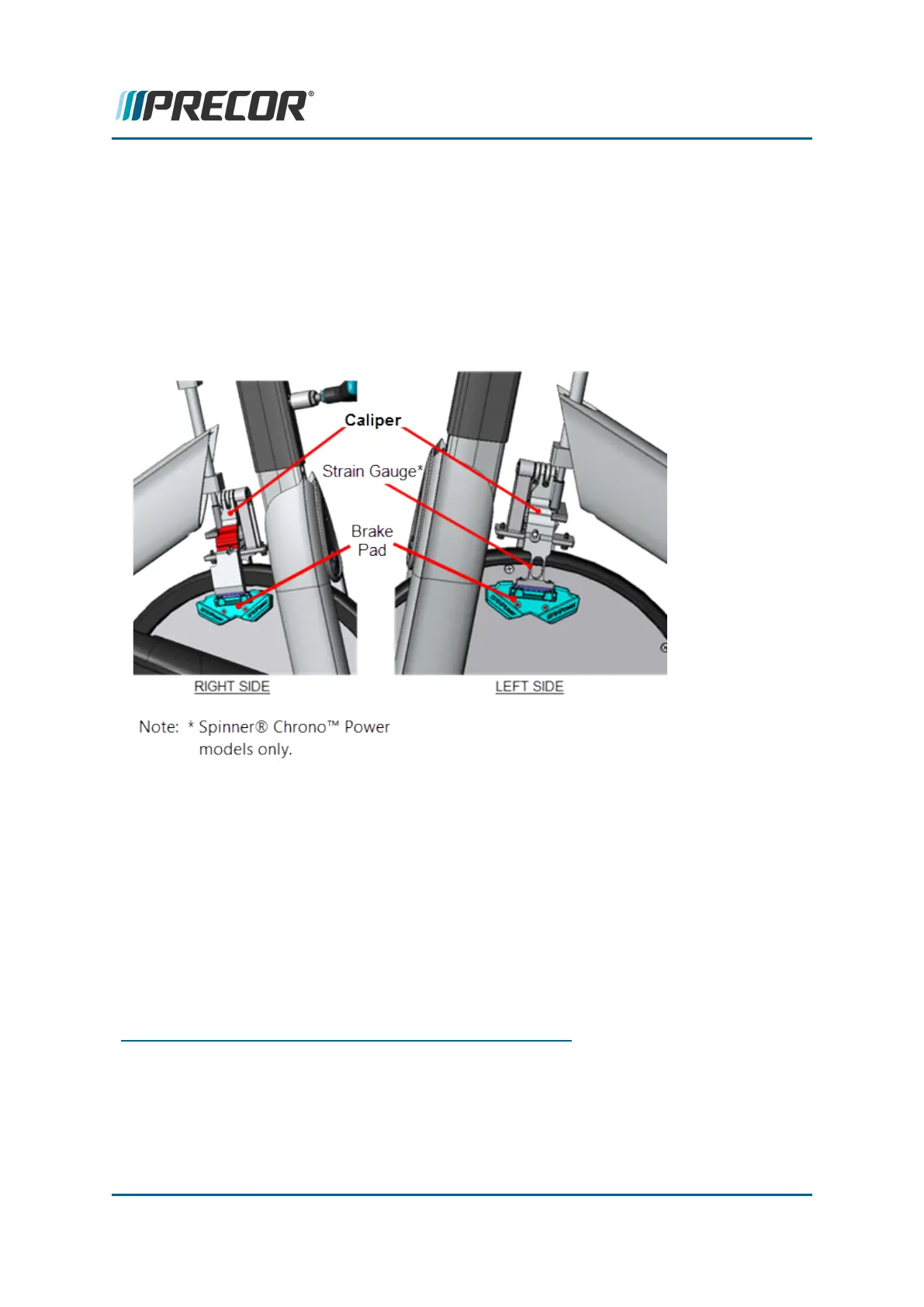
Strain gauge cable routing
(Spinner® Chrono™ Power models only)
Beginning from the strain gauge left side caliper, the cable crosses to the right side and
enters the right fork weldment upper cable access hole. From there the cable travels down
the right fork weldment exiting at the lower cable access hole traveling across the cross
member connecting to the LPCA
2
board strain gauge input connector.
1
Spinner® Chrono™ Power bike.
2
Lower Printed Circuit Assembly board; also refered to as the Lower PCA or simply as the
lower board. On treadmills, it is the console to base function interface and the motor con-
troller unit (MCU). On self-powered units, it is the lower PCA console to base function inter-
face.
Contact Precor Customer Support at support@precor.com or 800.786.8404 with
any questions.
Page 57
5 Replacement Procedures
Brake Caliper Assembly Replacement