CONTROLS & CONNECTIONS 3Owner’s Manual
49
Overview Getting
Started
Controls and
Connections
Cascading
Units
Technical
Information
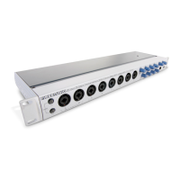
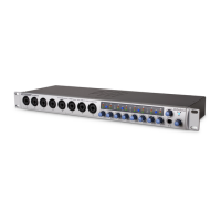
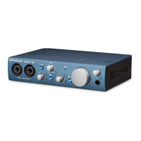
Front-Panel Layout 3.2
jacks of Channels 1 or 2. Active instruments have an
internal preamp and a line-level output and should
be plugged into a line-level input on the rear of the
FireStudio Mobile, not into a front-panel instrument
input. Plugging line-level sources into the instrument
inputs risks damage to the inputs and can result in a
very loud and often distorted audio signal.
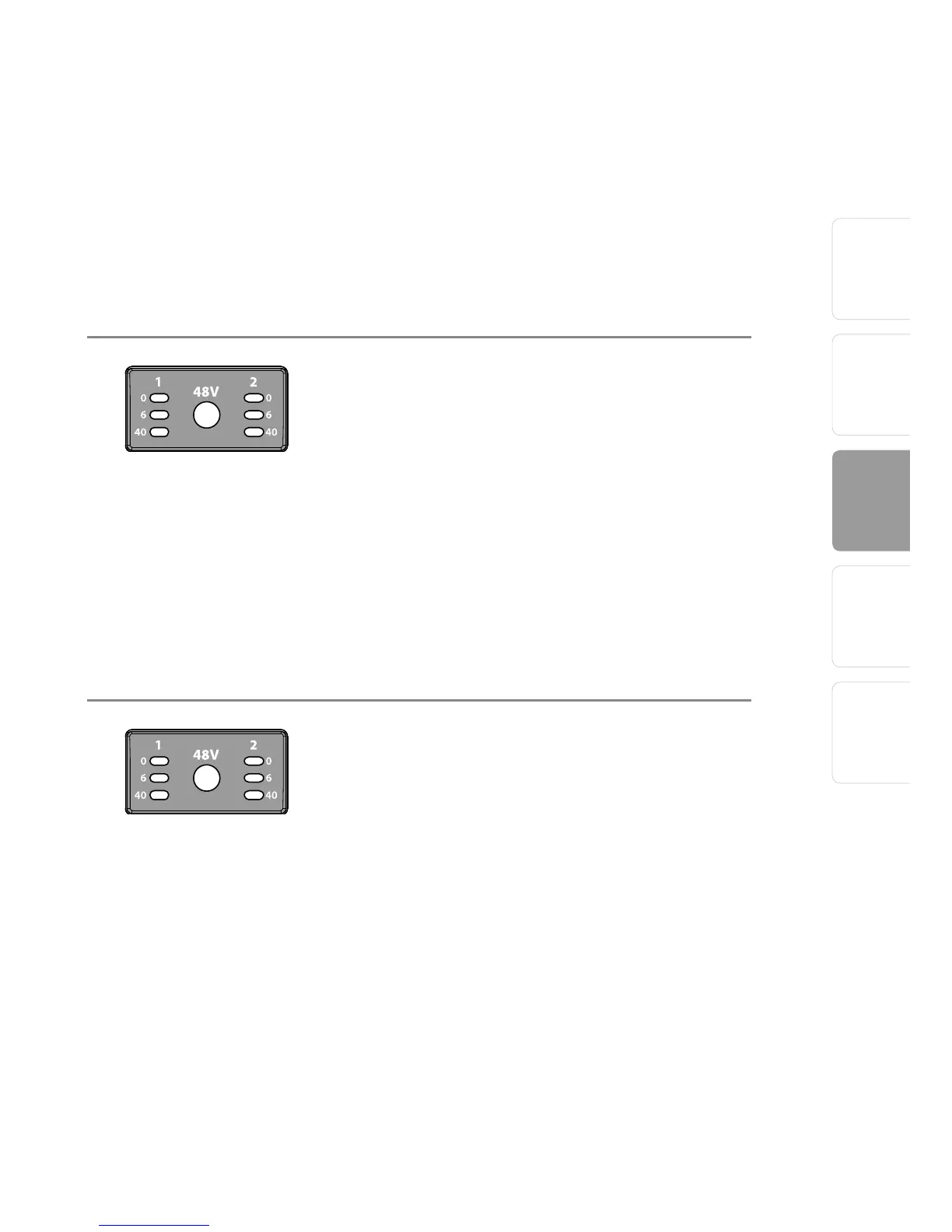
LED Meters/Clip Indicator. Channels 1 and 2
feature 3-LED level indicators. The green LED will
light up when an input signal from the XLR (Mic
input) or ¼” (Instrument input) reaches -40 dBFS
(-30 dBu). The yellow LED will light up when the
channel’s input signal reaches -6 dBFS (+4 dBu).
The red clip indicator LED will illuminate when
the channel’s input signal reaches 0 dBFS (+10
dBu). At this level, the signal will begin to overload
the converters and exhibit signs of clipping,
an undesirable type of distortion. Use the gain
controls to keep the signal below 0 dBFS.
48 Volt Phantom Power. The FireStudio Mobile
has 48V phantom power, available via a single
button switch on the front panel. Phantom power
is available whether your FireStudio Mobile is
powered by the FireWire bus or by its external
power supply.
• XLR-connector wiring for phantom power:
• Pin 1 = GND
• Pin 2 = +48V
• Pin 3 = +48V