27
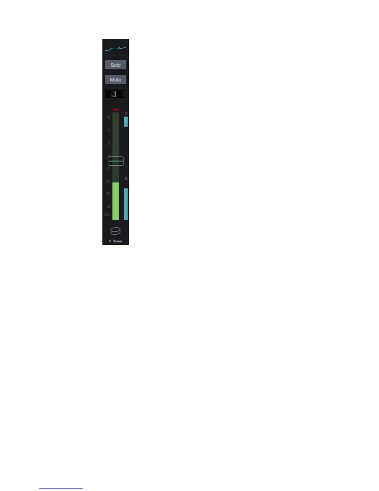
EQ Micro View. This section of the channel strip displays the EQ curve that’s
applied to the channel. It will also display the current value for the channel
fader or Pan control whenever they’re moved. This display reverts to the EQ
curve after you’ve finished interacting with the fader or Pan control.
Solo Button. When activated on a channel this button
illuminates and routes the channel to the Solo bus.
Soloed channels are routed to the solo bus by default and don’t affect the main
outputs. However, this can be changed to SIP (Solo In Place) in the settings.
Mute Button. This button illuminates when active
and mutes the channel it belongs to.
Pan. This adjust the position of the sound within the stereo
“field” by placing it to the left, right, or center.
When using LCR Panning mode the pan functionality will work as follows:
• Assign a channel to the Main L/R bus only: Stereo pan operates normally.
• Assign a channel to both the Main L/R and Center: Pan operates in LCR.
- Full left is left channel only.
- As you move toward the center on the pan control, the
signal begins to fade from the left only to the center.
- At the center pan position, the signal is only routed to the center bus.
- As the pan control is moved toward the right, the signal begins
to fade into the right channel and out of the center channel.
- At the full right position, the signal is in the right channel only.
• Assign a channel to the Main Center only: Pan has no affect
and the signal is routed only to the center channel.
Input Meter. This meter displays the level for the input signal for the channel.
Compressor Gain Reduction Meter. This meter displays a letter C when
a Fat Channel Compressor is active and provides a visual representation
of the amount of gain reduction applied to the input signal.
Noise Gate Gain Reduction Meter. This meter displays a letter G when
a Fat Channel Noise Gate is active and provides a visual representation
of the amount of gain reduction applied to the input signal.
Fader. The fader adjusts the signal level for the channel.
The fader will be blue when controlling the Main mix, yellow when
controlling Aux mixes, and purple when controlling FX mixes.
Channel ID Icon. This displays the channel number along
with the channel name and Channel Type image.
Clicking or tapping this part of the Channel Strip also selects the channel.
Note: The Channel Type Image and a default type name are set when you choose
the Channel Type. For more information, refer to Channel Type on page Page 37.