Pos. Name Image Description
■
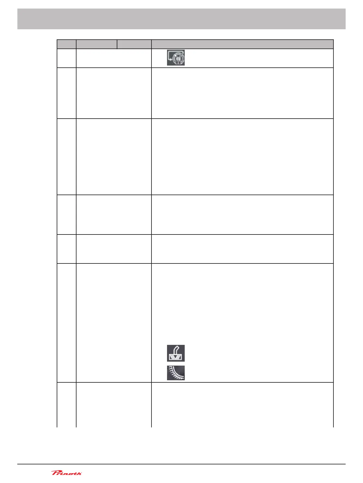
Turn cable traction force rotary switch to MIN
31 Rear tiller side wings up/
down
If the respective symbol lights, the position of the side wings on
the rear tiller is displayed:
■ Wing
upwards continuously lit white = Left / right side wing
up
■ Wing downwards continuously lit green = Left / right side
wing down
33 Rear tiller (horizontal)
center/floating/right/left
position
The status of the rear tiller is indicated when the respective sym-
bol lights up:
■ Arrows
pointing to each other continuously lit white = Center
position
■ Shaft continuously lit white = Floating position
■ Right arrow continuously lit white = Rear tiller swivelled to
the right
■ Left arrow continuously lit white = Rear tiller swivelled to the
left
34 Operational readiness of
the attachments
If the rear tiller lamp is continuously lit grey, the operational readi-
ness of the attachments is activated.
If
the grey rear tiller lamp goes out, the operational readiness of
the attachments is deactivated.
If the rear tiller lamp is continuously lit red, there is a malfunction.
35 Tiller cutting depth in % Indicates the tiller cutting depth in the range from 0
to 100:
■ 0 = Minimum tiller cutting depth
■ 100 = Maximum tiller cutting depth
36 Cutter shaft speed in %
and direction of rotation
When the respective symbol is lit, the status of the tiller shaft and
the set value from 0 to 100 is displayed:
■ Tiller shaft blinks green = Tiller shaft active but not rotating
■ Tiller shaft with arrow in counter-clockwise direction green =
Tiller shaft turning in normal direction of rotation
■ Tiller shaft with arrow in clockwise direction orange = Tiller
shaft turning in counter direction
If other front attachments are in use, the following symbols are
displayed:
■
= front-end blower
■
= Half-pipe front attachment
37 Contact pressure / float-
ing position / counter
pressure for rear tiller
(vertical) and setting val-
ue in %
When the respective symbol is lit, the rear tiller status is indicated
and the respective set value from 0 to 100 is displayed:
■
Down arrow continuously lit green = Down pressure
■ Wave continuously lit green = Floating position
■ Up arrow continuously lit green = Counter pressure
Operating and Maintenance Manual
Snow groomer BISON
80 (255)
6 - Display
BISON 908930245 - 30367