ProMinent
®
Page 16
4.2.4 Connecting coaxial cable
The pH resp. redox probe is connected via a coaxial cable:
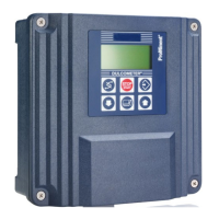
왘 Strip back to reveal cable shield (reference electrode) in accordance with
fig. 7 (left) and clamp using the shield clip.
The shield clip is connected internally to terminal 3.
Under normal circumstances measuring can be carried out without
connecting a liquid reference potential. In this case provide wire jumpers
between terminals 1 and 2.
When electrical conditions are more complex a potential plug should be
connected to terminal 1. Terminal 2 is left free.
The appendix contains an overview of connection options (terminal
connection plan).
4.2.5 Connecting terminals
왘 Remove insulation from cable ends as shown in fig. 7 (right) and attach
end crimps to each core.
왘 Connect the cables in accordance with the terminal connection plan.
IMPORTANT
• Do not operate PROFIBUS
®
variants at voltages over 30 V.
•
Connect PROFIBUS
®
variant power supplies via terminals 3
and 4 on the PROFIBUS
®
circuit board in the back section,
not terminals 7 and 8 in the front section.
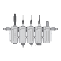
NOTE
• The terminal connection plan is given in the appendix.
There is also a panel giving connection information affixed
to the housing near the terminals (fig. 6, and fig. 8).
• Push the cable through the housing until the front section
can be moved up and down easily.
• If the LC display is too weak, reduce the brightness using
the up arrow key
. If the display is too dark, increase the
brightness using the down arrow key .
Fig. 7 Fig. 8
33
12
30
7
7
3459_4
Cl/ClO /O
3
2
-
+
4to20mA
shield
(gr) Pt1000 - /sig.gnd.
(wth) Pt1000 +
(bl) +U
---
(blk)-U
(br) meas.sig.
Pt100 -
Pt100 +
---
liquid pot.
ref.el.
glass el.
pH/ORP
8
6
5
4
3
2
7
1
Assembly and installation
BA_DM_163_03_08_GB.p65 26.03.2008, 10:20 Uhr16