ProMinent
®
Page 14
4.2.1 Wall mounting
왘 Unfasten the four housing screws
왘 Lift the front section slightly forwards and then swing open to the left.
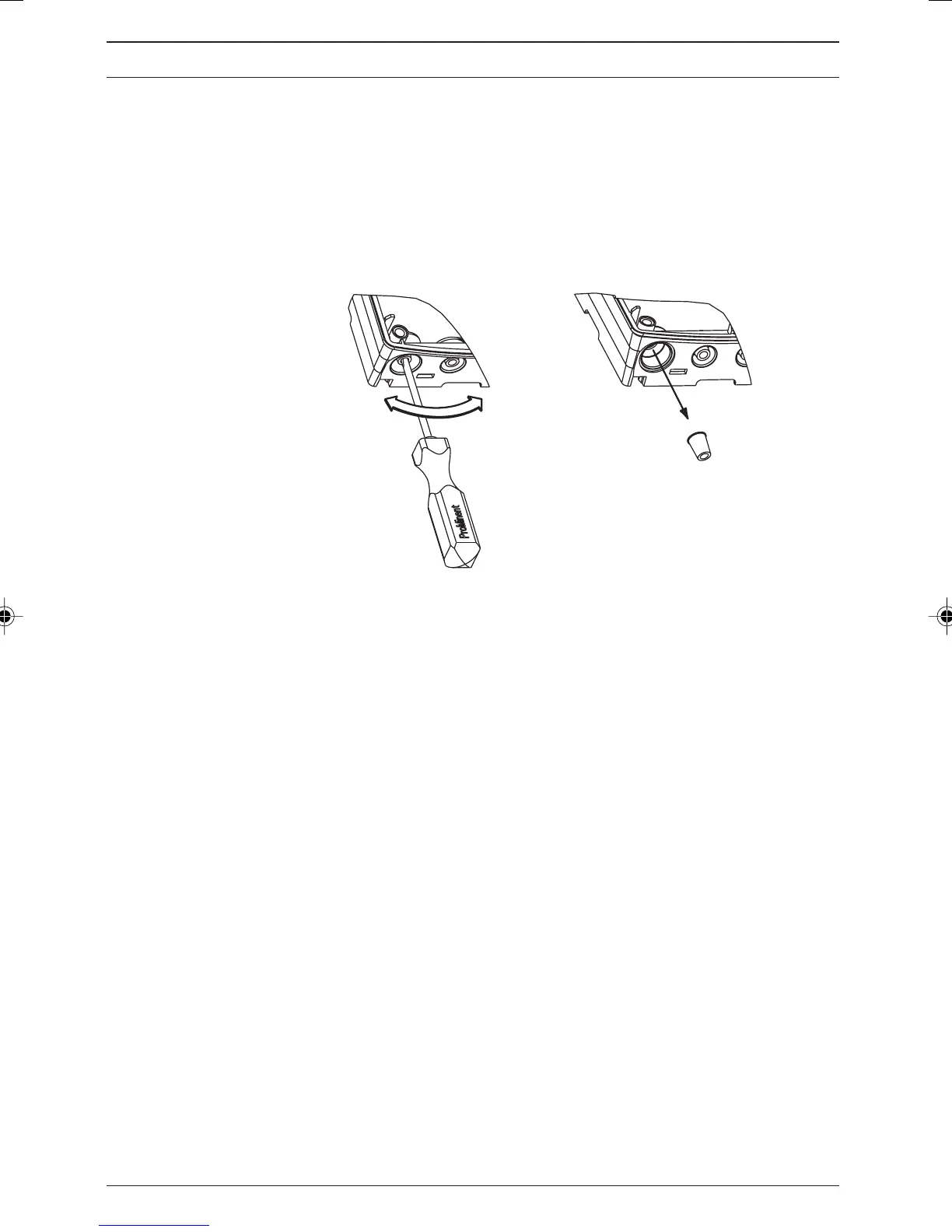
왘 Pierce threaded cable apertures at the bottom of the rear side as required
(fig. 5).
Fig. 5
3468_4
NOTE
• The large gland (M 20 x 1.5) is intended for the sensor
cable.
• Feed the power cable leftwards through the smaller
threaded connector (M 16 x 1.5). Follow with the other
sensor cables (e.g. PT 1000).
왘 Tighten the threaded connectors (fig. 6, ➀) as required.
왘 Use reducers as required (fig. 6, ➁) to adapt the sizes of the threaded
connectors to the actual cable diameters.
왘 Feed the cables into the threaded connectors.
왘 Now proceed according to 4.2.4 Connecting coaxial cable and
4.2.5 Connecting terminals.
Then follow the steps below:
왘 Tighten the locking screws (fig. 6, ➂) for the threaded connectors.
왘 Swing the front section onto the back section.
Assembly and installation
BA_DM_163_03_08_GB.p65 26.03.2008, 10:20 Uhr14